English
 Español
How Robotic Polishing Systems Compensate for Tool Wear and Maintain Stable Contact Force
Introduction
An industrial robot can repeat the same programmed path thousands of times, but the abrasive tool does not remain unchanged. Grinding belts become dull, flap wheels lose diameter, buffing wheels compress and wear, and brushes gradually change shape. If the system does not account for these changes, the first part and the last part processed with the same tool may have noticeably different surfaces.
This is why a reliable robotic grinding and polishing system needs more than accurate robot motion. It also needs a practical strategy for contact-force control, abrasive-tool wear compensation, tool replacement and process verification.
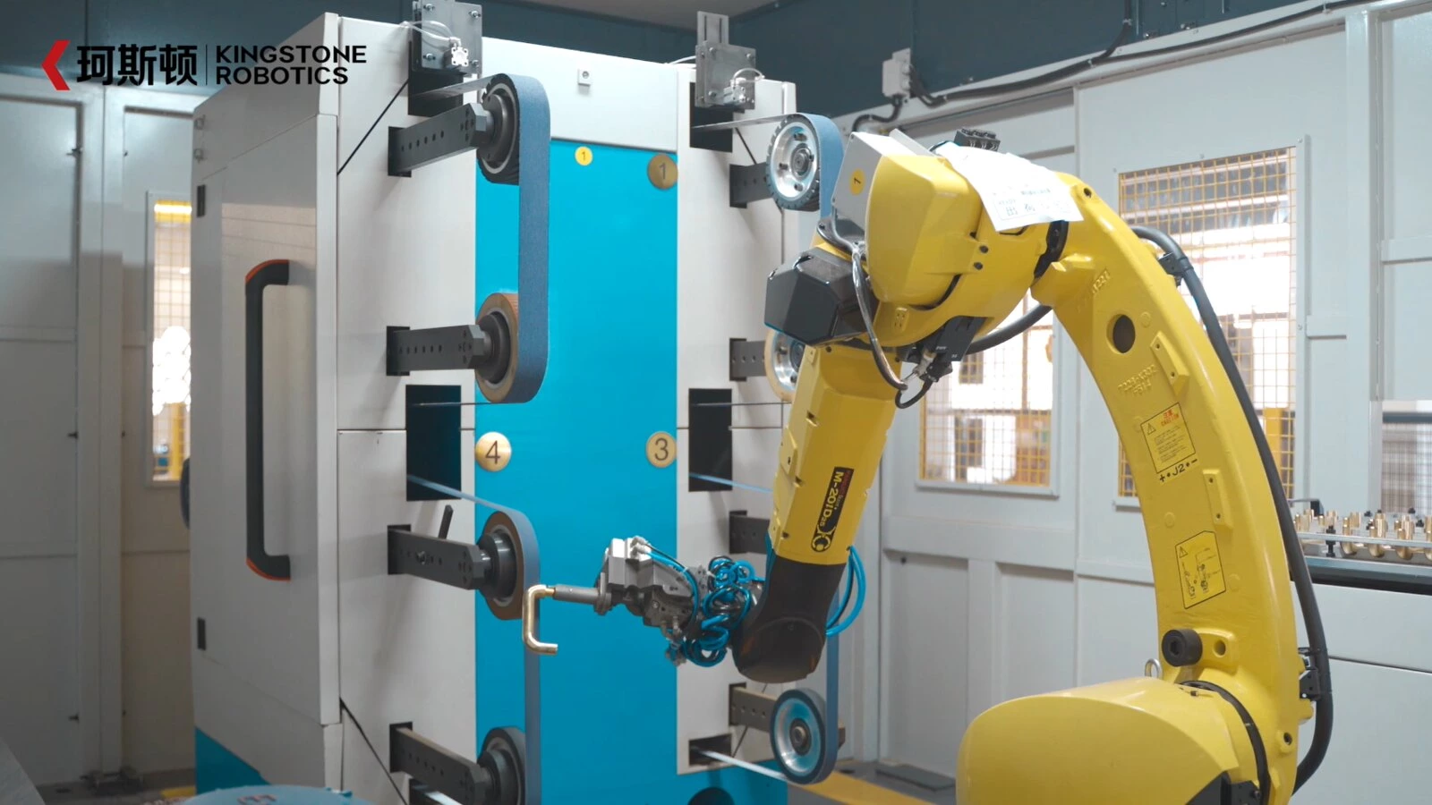
The following short video shows a robot performing abrasive belt grinding on a hammer head. In this type of repetitive grinding application, maintaining stable contact force and managing abrasive-belt wear are important for consistent material removal and surface quality from part to part.
These functions work together, but they do not all solve the same problem. Force control helps the tool remain in stable contact with the workpiece. Tool-wear compensation accounts for changes in tool position, size and cutting behavior. Process monitoring helps determine when compensation is still effective and when the abrasive should be replaced.
Why Abrasive Tool Wear Changes the Polishing Result
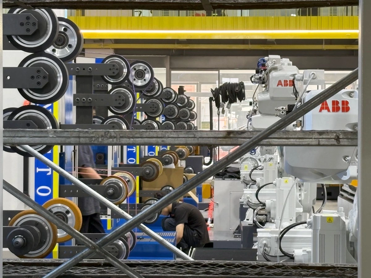
Abrasive tools remove material through thousands of cutting points. During production, those cutting points become dull, loaded with debris or physically worn away. The way the tool contacts the part also changes.
Depending on the abrasive and application, wear may cause:
- Lower material-removal rates
- Longer processing times
- Changes in surface roughness or gloss
- More heat at the contact area
- Visible polishing lines or uneven blending
- A smaller wheel diameter or a different contact position
- More pressure being required to achieve the same apparent result
The robot may still be following its original path perfectly. The inconsistency comes from the process around the robot. For this reason, repeatable motion alone cannot guarantee repeatable finishing quality.
Force Control and Tool-Wear Compensation Are Not the Same
These two terms are often discussed together, but the distinction is important.
Force control regulates the contact load between the abrasive tool and the workpiece. When the part position or surface varies slightly, the system can adjust its position or compliance to maintain the specified contact force.
Tool-wear compensation adjusts for changes caused by the abrasive itself. For example, when a polishing wheel becomes smaller, the programmed contact point may need to move. When a belt becomes dull, the system may need to change a process parameter or instruct the operator to replace the belt.
Stable force does not automatically mean that the abrasive is still cutting correctly. A worn belt can maintain the commanded contact force while producing a slower, hotter or less uniform process. This is why a complete wear-management strategy cannot rely on force feedback alone.
How Robotic Polishing Systems Maintain Stable Contact Force
The suitable control method depends on the workpiece, abrasive, required finish, allowable variation and production volume. A system may use one method or a combination of methods.
1. Sensor-Based Active Force Control
A force or force-torque sensor measures the load at the contact point. The controller compares the actual force with the programmed value and makes small position adjustments while the robot follows the polishing path.
This approach is useful for curved surfaces, irregular castings and applications where the robot needs to follow small surface variations. The response, force range and control parameters must be tuned for the actual tool and material. An unstable or overly aggressive setting can create oscillation, edge damage or inconsistent removal.
2. Compliant or Floating Tooling
Pneumatic, spring-based or actively controlled compliance allows the tool to move slightly when the surface position changes. Instead of treating the robot and tool as completely rigid, the compliant unit absorbs small variations and helps maintain contact.
This can be effective for sanding, polishing, brushing and light deburring. The amount and direction of compliance must match the process. Too little compliance may not absorb the variation; too much can reduce path accuracy or make edges difficult to control.
3. Controlled Grinding or Polishing Equipment
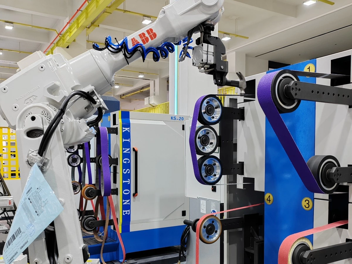
When the robot holds the workpiece against a stationary belt sander or polishing wheel, the process equipment can also provide controlled movement or pressure. The abrasive unit may use a floating mechanism, servo axis or pressure-control device so the contact point can respond to the workpiece.
This configuration is common for faucets, handles, castings and other small or medium-sized components that the robot can grip and rotate.
4. A Hybrid Control Strategy
Many production applications benefit from combining accurate robot paths, mechanical compliance and monitored process parameters. The robot provides repeatable motion, the compliant device handles small variations, and the control system monitors whether the process remains within the approved range.
The best configuration is not necessarily the most complicated. It is the one validated on representative parts and capable of maintaining the required finish throughout normal production.
How Robotic Systems Compensate for Abrasive Tool Wear
1. Planned Tool-Life Limits
The simplest dependable method is to establish a replacement limit based on production testing. The system records operating time, part quantity, process cycles or polishing distance and generates a warning when the validated limit is reached.
This approach is practical when the parts and incoming surface condition are relatively stable. The replacement limit should be based on test results rather than an arbitrary number. A belt used for heavy casting-line removal will not have the same life as a belt used for light surface blending.
2. Tool Position or Diameter Compensation
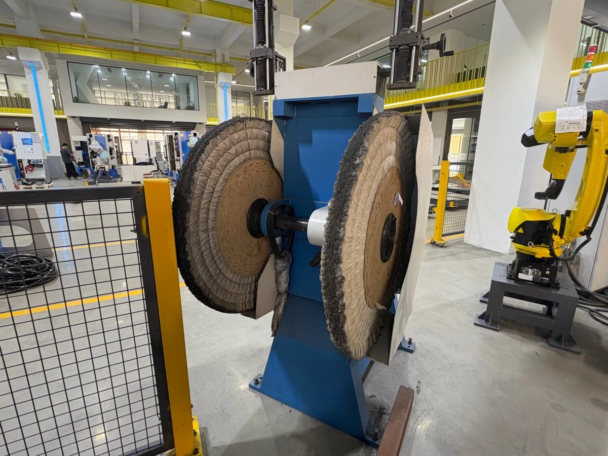
Flap wheels, buffing wheels and other rotating tools lose diameter during use. If the robot continues to move to the original contact point, the actual pressure and processing position will change.
The system can compensate by updating the tool center point, moving the polishing unit, using a measuring routine or applying a calculated offset after a defined amount of use. The selected method depends on the required accuracy, wheel construction and cell design.
3. Controlled Parameter Adjustment
Within a validated range, the process may adjust path speed, contact force, wheel speed or number of passes to maintain the required result. These adjustments should be limited and tested.
Continuously increasing force is not a substitute for replacing a worn abrasive. Excessive pressure can generate heat, deform thin parts, round edges, overload equipment or produce a worse surface. Once the tool reaches its approved wear limit, replacement is usually the more stable choice.
4. Tool Dressing, Cleaning or Automatic Replacement
Some abrasive tools can be dressed or cleaned to restore their working surface. Other applications may use an automatic tool changer or multiple abrasive stations so the robot can continue production with less manual intervention.
Whether this level of automation is worthwhile depends on cycle time, tool-change frequency, production volume and the cost of stopping the cell.
5. Quality Checks at Defined Intervals
Tool compensation should be confirmed by the finished part, not only by machine data. Manufacturers may inspect surface roughness, visual appearance, dimensions, remaining burrs or other application-specific quality points after a defined number of cycles.
The inspection result helps engineers refine the replacement limit and determine whether the compensation strategy remains reliable from a new tool to the end of its approved life.
Can a Robot Automatically Detect When a Polishing Tool Is Worn Out?
It can, but there is no single signal that works for every abrasive and every polishing process.
Common monitoring methods include:
- Operating time or processed-part count
- Measured wheel diameter or tool position
- Force and torque trends
- Spindle or motor-current trends
- Tool-contact position and compensation distance
- Surface inspection or sample testing
- Operator confirmation after a wear alarm
Changes in friction may appear in force, torque or motor-load data, but these signals can also change because of part variation, casting flash, contamination, tool loading or an incorrect fixture position. The system therefore needs baseline data and approved thresholds established during process testing.
For many factories, the most reliable solution combines a conservative part-count or operating-time limit with position compensation and periodic quality checks. More demanding applications may add direct tool measurement, real-time load monitoring or automatic inspection.
Wear Strategies for Different Polishing and Grinding Tools
Abrasive Belts
Belts usually lose cutting ability before a major dimensional change becomes visible. Belt tension, tracking, loading and abrasive dulling all affect performance. A typical strategy combines a validated replacement interval with force or equipment-position control and clear operator alarms.
Flap Wheels and Sanding Wheels
These tools gradually lose diameter and may also change stiffness as they wear. The system may need both position compensation and a replacement limit. Wheel speed and contact geometry should be checked throughout the approved wear range.
Cloth and Sisal Buffing Wheels
Buffing results depend on wheel condition, diameter, compression, speed and polishing-compound application. Stable compound delivery and controlled contact are therefore part of the process. Diameter compensation alone cannot correct an overloaded, contaminated or damaged wheel.
Grinding Wheels, Brushes and Deburring Tools
Rigid grinding tools may require dimensional measurement, dressing or replacement. Brushes can lose bristle length and change contact behavior. Deburring cutters may become dull and increase the process load. Each tool needs its own wear indicators and maintenance rules.
A Practical Commissioning Process
Wear compensation should be developed during process testing, not added after the machine has been delivered. A practical commissioning sequence includes:
- Collecting representative parts from different production batches
- Defining the required appearance, roughness, dimensions and cycle time
- Selecting the abrasive sequence and contact method
- Establishing baseline force, speed, path and tool-life data
- Defining allowable compensation ranges and replacement thresholds
- Testing parts with a new, partly worn and near-limit abrasive tool
- Confirming the finished quality at each stage
- Creating clear alarms, replacement instructions and maintenance records
Testing only the first few parts with a new abrasive is not enough. The customer needs to know how the cell behaves as the tool approaches the end of its approved service life.
Questions Buyers Should Ask a Robotic Polishing Supplier
When comparing systems, manufacturers should ask:
- How is contact force generated and controlled?
- Which types of part variation can the system accommodate?
- How does the system compensate for wheel-diameter or tool-position changes?
- How is abrasive life established during sample testing?
- What tells the operator that a tool should be changed?
- Can process limits be adjusted for different product models?
- What happens when force, position or motor load exceeds the approved range?
- How are replacement tools calibrated?
- Which daily and periodic maintenance tasks are required?
Tool-wear management is only one part of the investment decision. This guide on how to evaluate a robotic polishing system covers additional questions about fixtures, safety, programming, integration and after-sales support.
Information Needed Before Designing the System
A supplier cannot define the correct force-control or wear-compensation method from a product name alone. Useful project information includes:
- Workpiece material, dimensions and weight
- Drawings, 3D models and clear photographs
- Several samples showing normal production variation
- Current grinding or polishing steps and abrasives
- Defects that must be removed
- Required surface roughness or visual standard
- Areas that must not be processed
- Target cycle time and daily output
- Product models and expected changeover frequency
- Downstream coating, plating, anodizing or assembly requirements
Part location also affects force stability. If the workpiece moves or sits differently in each cycle, the control system must compensate for a problem that should first be reduced mechanically. Read more about fixture design for robotic grinding and polishing.
Kingstone Robotics' Approach
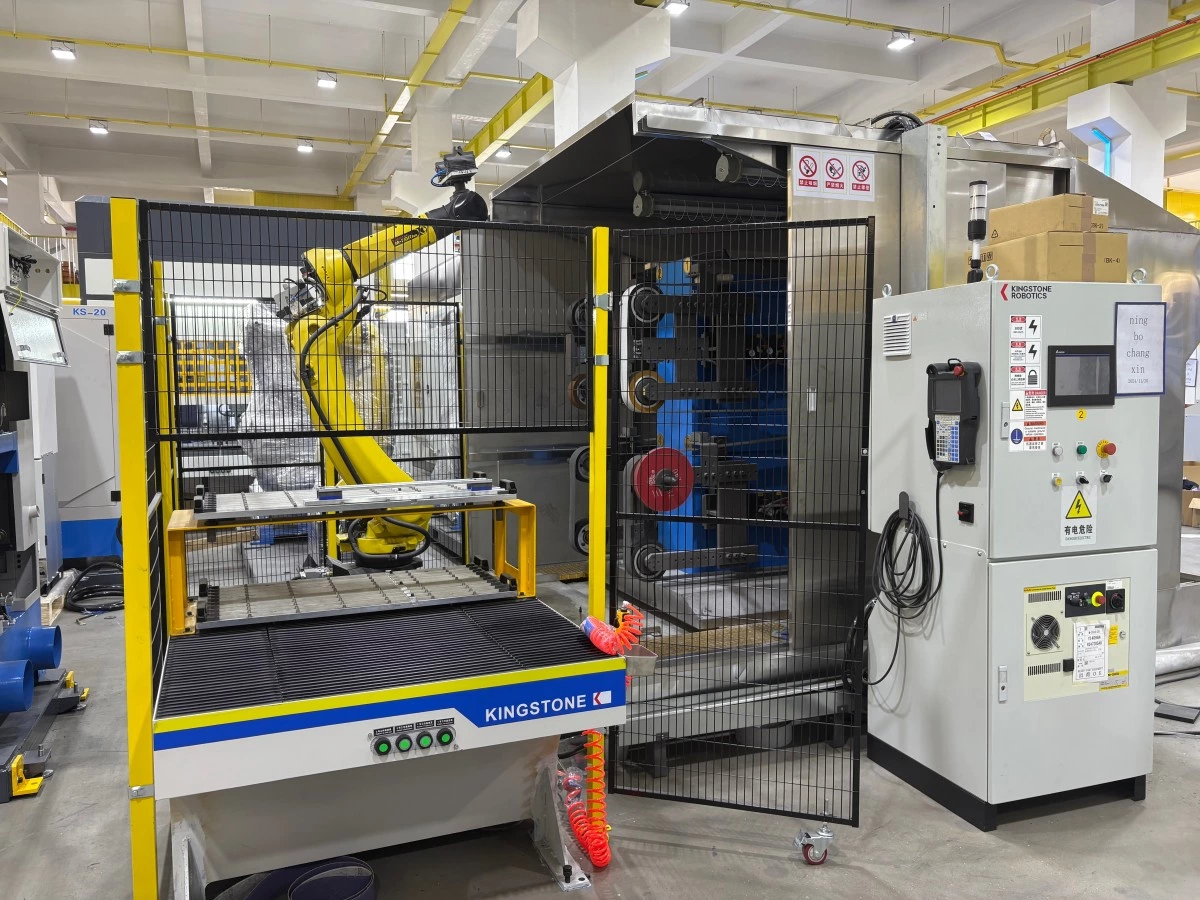
Kingstone Robotics develops customized grinding, polishing and deburring systems around the customer's actual parts and finishing requirements. During project evaluation, the robot, abrasive equipment, force-control method, fixture, tool-wear strategy, loading method, safety enclosure and dust collection are considered as one integrated process.
Depending on the application, the solution may include controlled grinding or polishing stations, compliant tooling, force monitoring, position compensation, tool-life alarms, automatic compound application, multiple abrasive stages and production-data records.
For casting applications, manufacturers can also review our casting-parts grinding and polishing solution.
Conclusion
Consistent robotic polishing depends on controlling a process that changes over time. The robot path may remain the same, but the abrasive condition, contact geometry and cutting behavior do not.
Force control helps maintain stable contact. Position compensation accounts for dimensional wear. Tool-life limits and process monitoring determine when correction is still acceptable and when the abrasive should be replaced. When these elements are validated together on representative samples, manufacturers can achieve more predictable surface quality across the full production run.
If you are planning a robotic grinding or polishing project, contact Kingstone Robotics and send us your part drawings, photographs, samples, required finish and target cycle time. Our engineering team will evaluate a suitable process and automation configuration for your application.
Frequently Asked Questions
1. Does force control eliminate abrasive tool wear?
No. Force control helps maintain the commanded contact load, but the abrasive will still become dull, loaded or dimensionally worn. The system also needs a replacement and compensation strategy.
2. Can a robot know automatically when a sanding belt is worn out?
Yes, when the application has validated monitoring rules. These may use operating time, part count, force or motor-load trends and quality checks. Belt condition is application-specific, so the limits should be established through testing.
3. Can higher pressure compensate for a dull abrasive?
Only within a limited, tested range. Excessive pressure may increase heat, damage edges, deform the part or overload the equipment. Replacing the abrasive is usually more stable once its approved limit is reached.
4. Is tool-diameter compensation required for every polishing process?
Not always. It is most relevant when wheel or brush wear changes the actual contact position enough to affect force, coverage or surface quality. The required method depends on the tool and process tolerance.
5. Can one force-control setting be used for different products?
Different materials, geometries, abrasives and finish requirements often need different settings. Each product program should use validated force, speed, path and wear limits.
6. What samples should be provided for process testing?
Provide several parts from normal production batches, including realistic surface and dimensional variation. A drawing or ideal sample alone may not represent the conditions the robotic system must handle in daily production.