English
 Español
 French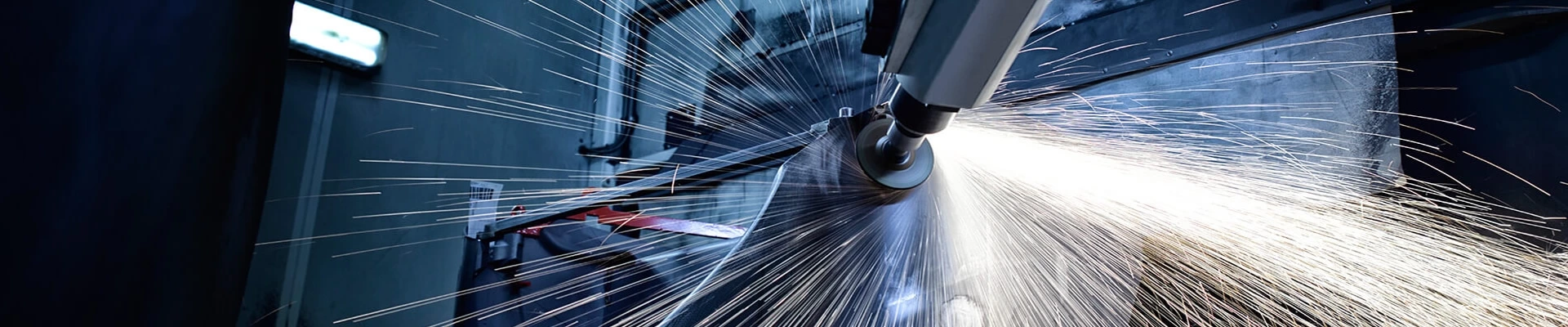
Why Fixture Design Matters in Robotic Grinding and Polishing Systems
Introduction
A robot can repeat the same movement thousands of times. That does not guarantee that every finished part will look the same.
If a workpiece sits slightly higher, rotates during contact, or vibrates against the abrasive tool, the robot will process a different area even though its program has not changed. The result may be uneven material removal, visible polishing lines, missed edges or excessive grinding in one location.
This is why the fixture is not a minor accessory. In a complete robotic grinding and polishing system, the fixture establishes the position of the part, supports it against processing forces and keeps the required surfaces accessible to the tool.
Good fixture design begins with the part and the finishing process—not with a standard clamp selected after the robot layout is complete.
Robotic Grinding and Polishing Cell in Operation
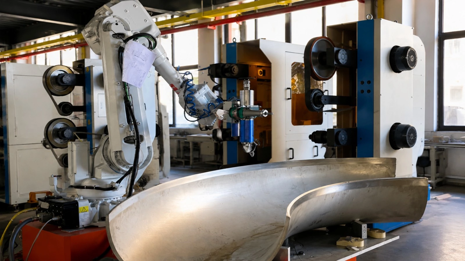
This short video shows an integrated robotic grinding and polishing cell in operation. While the robot and abrasive stations are the most visible components, consistent finishing also depends on how accurately the workpiece is positioned, supported and presented to the tool.
What Does a Fixture Need to Do?
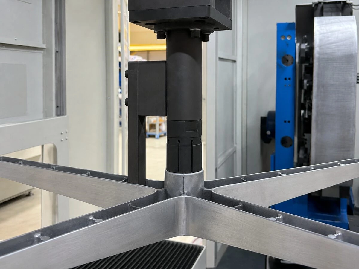
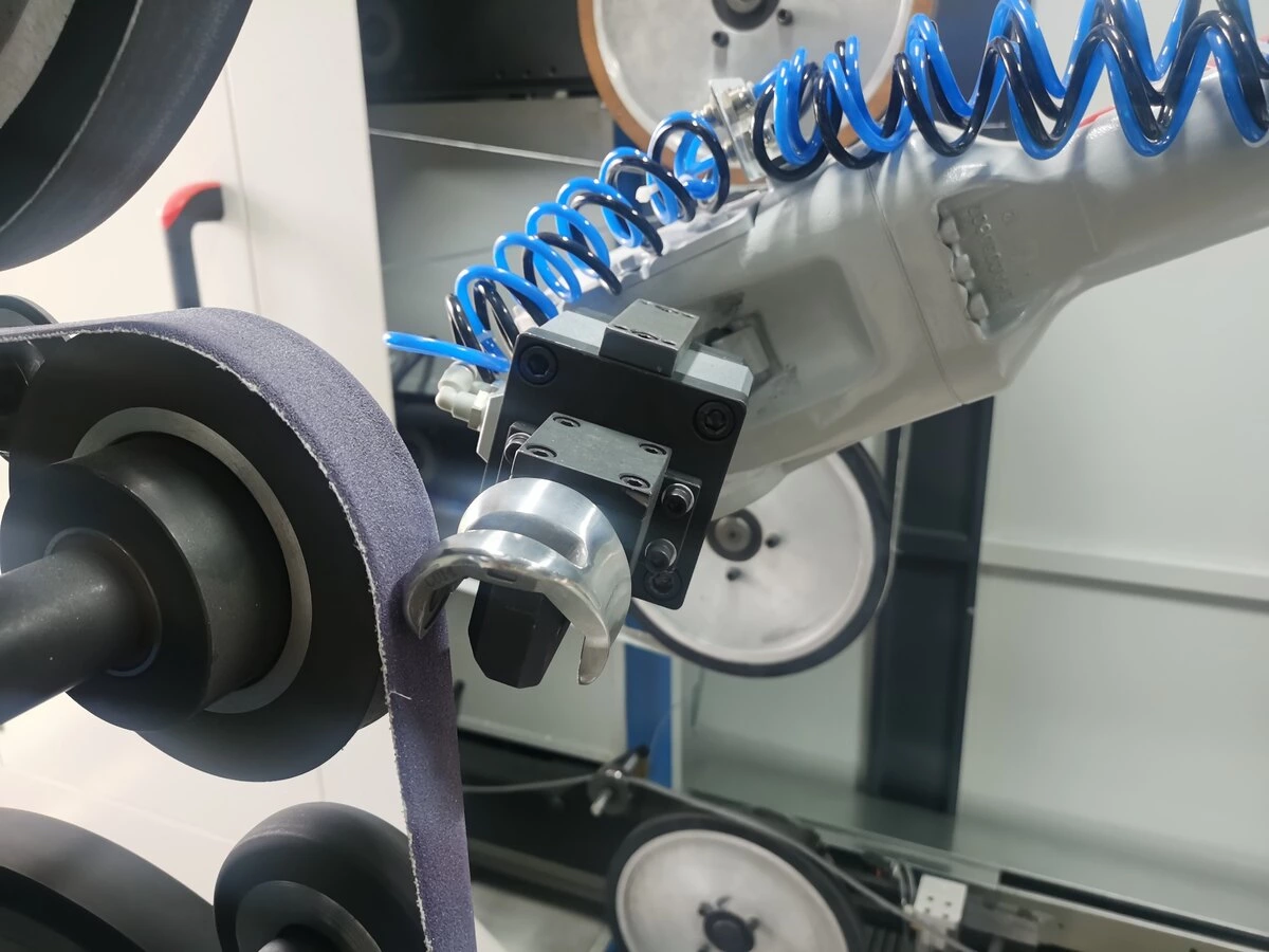
The fixture creates a repeatable relationship between the workpiece, robot and abrasive tool. Depending on the system configuration, it may be a stationary device on a worktable, a fixture mounted on a rotary positioner, or a gripper that allows the robot to carry the part to a fixed grinding or polishing machine.
A production fixture should be able to:
-
Locate every part from reliable reference points
-
Hold the workpiece securely during grinding or polishing
-
Resist movement and vibration under contact force
-
Protect visible or already-finished surfaces
-
Leave enough space for the belt, wheel or deburring tool to reach the processing areas
-
Allow safe and repeatable loading and unloading
-
Accommodate normal variation in cast, forged or fabricated parts
-
Remain reliable when exposed to abrasive dust and production debris
These functions need to work together. A fixture may hold the part very tightly, but it is still unsuitable if a clamp blocks the robot path or leaves a visible pressure mark on the product.
How Fixture Design Affects Surface Quality
1. Repeatable Part Positioning
Robots follow programmed paths relative to a defined coordinate system. If the position of the workpiece changes from one cycle to the next, the contact point between the part and the abrasive also changes.
The fixture therefore needs clear locating features, or datums, that place every part in the same practical working position. Whenever possible, these datums should be based on stable part features rather than rough, irregular or easily deformed surfaces.
This is especially important when the process includes edge grinding, weld-seam removal or polishing around narrow transitions. A small positional change can become visible when the robot reaches a corner or blends two surfaces.
2. Support Against Grinding and Polishing Forces
Grinding belts, flap wheels and buffing wheels all apply force to the workpiece. The direction and level of that force change as the robot moves around the part.
If the workpiece is insufficiently supported, it may shift, flex or vibrate. Typical results include chatter marks, waves, inconsistent edge removal and variations in gloss. Adding more clamping force is not always the answer. The fixture needs support in the correct locations so that processing loads are transferred without distorting the part.
3. Clear Access to Every Processing Area
A fixture must hold the part without occupying the same space needed by the robot or abrasive tool.
During layout design, engineers need to consider:
-
The diameter and width of the grinding or polishing tool
-
The approach angle needed for each surface
-
Robot wrist and arm clearance
-
Tool wear and changes in wheel diameter
-
Space required for tool replacement and maintenance
-
Possible collision zones during loading and processing
A clamp that looks clear in a static drawing may still interfere with the robot when the tool approaches at an angle. Tool access should therefore be checked across the entire programmed path.
4. Protection of Visible Surfaces
The fixture should avoid clamping on cosmetic surfaces whenever another stable location is available. Contact pads may also be needed to distribute pressure or prevent metal-to-metal marking.
The pad material must suit the process. A soft pad can protect the surface, but it can also compress, collect abrasive particles or reduce positioning accuracy. The correct choice depends on the part material, clamping force, surface requirement and production environment.
5. Reliable Loading and Cycle Time
Fixture design also affects daily production efficiency. Operators or automatic loading equipment must be able to place the part correctly without repeated adjustment.
For lower-volume production, a simple manual clamp may be sufficient. For repeated medium- or high-volume production, pneumatic or hydraulic clamping can shorten handling time and provide more consistent operation. Part-presence sensors, clamp-position sensors and mistake-proof locating features can also help prevent an incomplete loading cycle.
The fastest clamp is not necessarily the best fixture. Loading speed, positioning accuracy, operator safety and long-term reliability all need to be considered together.
Fixture Strategies for Different Robotic Configurations
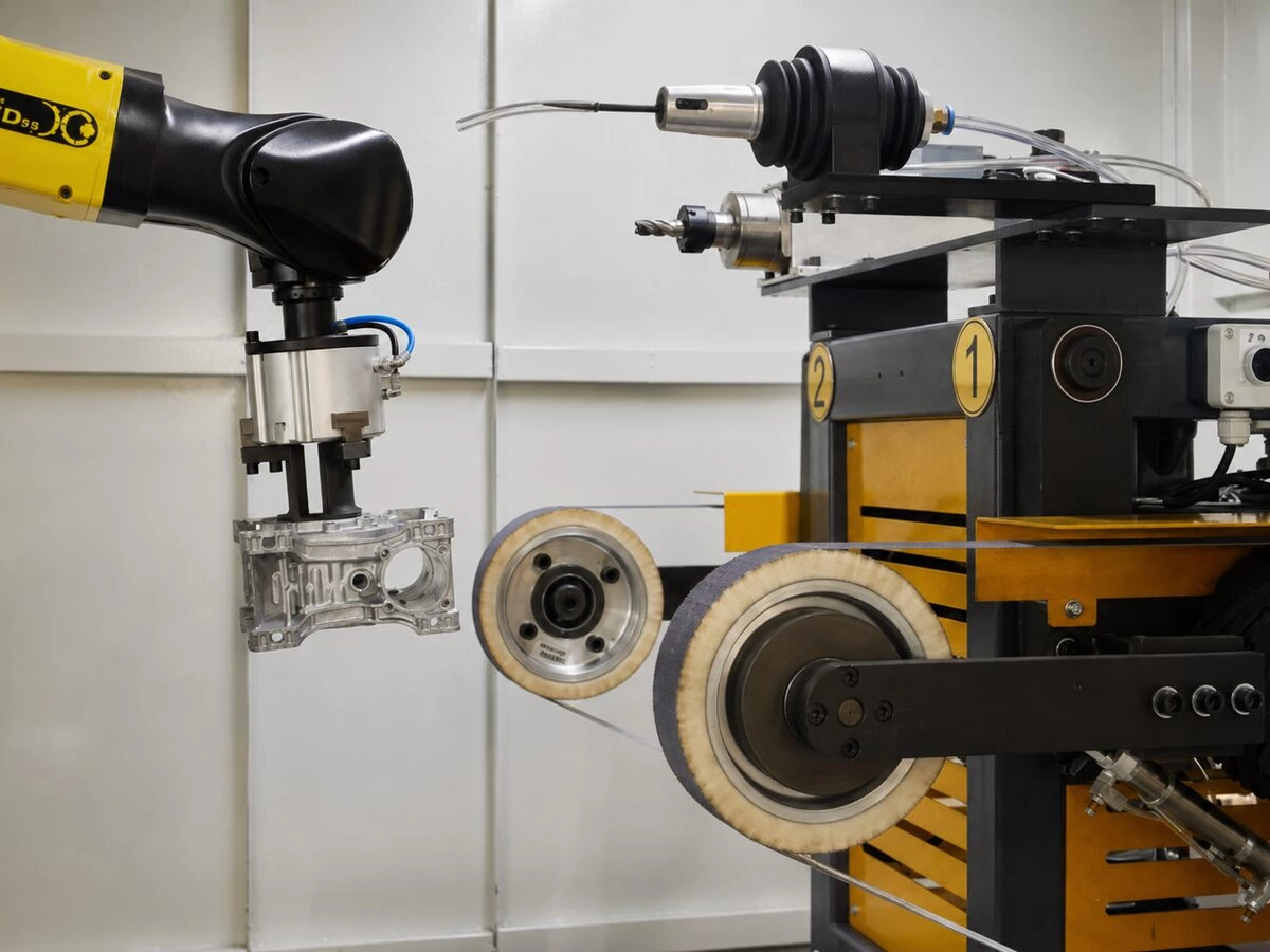
There is no single fixture layout for every finishing application. The correct strategy depends on part size, weight, geometry, processing areas and production flow.
Robot Holds the Workpiece
In many applications involving faucets, handles and other small or medium-sized components, the robot grips the workpiece and presents it to a fixed belt sander or polishing wheel.
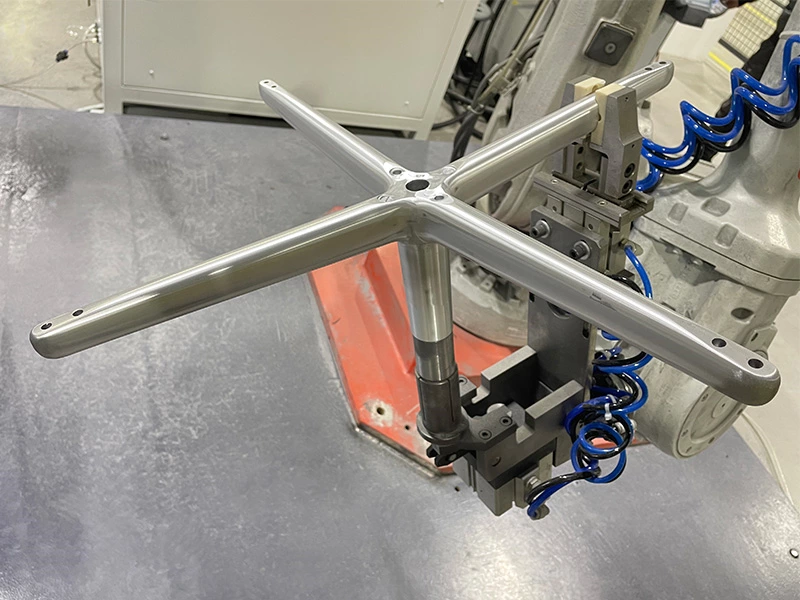
Here, the end-of-arm gripper acts as the main fixture. It must hold the component firmly while allowing the robot to rotate it through different angles. Grip location, part weight, center of gravity, wrist clearance and the direction of contact force all influence the design.
This configuration is commonly used in a robot grinding unit when several contours need to be processed against one or more fixed abrasive stations.
Fixture Holds the Workpiece
For larger, heavier or difficult-to-grip components, the part is often secured on a table or positioner while the robot carries the grinding or deburring tool.
The fixture needs enough rigidity to absorb processing forces and may require a rotary positioner to expose different faces. This approach is often suitable for large castings, housings and structural parts. A robot deburring unit may use this arrangement to remove flash, gates, sharp edges or parting lines from cast and machined components.
Multi-Station or Positioner-Based Fixtures
Some cells use two or more fixture stations so that one part can be loaded while another is being processed. Other systems use rotary tables or servo positioners to bring difficult surfaces into the robot's working range.
These layouts can improve production flow, but they also require accurate station alignment, reliable interlocks and enough clearance between the robot, fixture and operator loading area.
Common Fixture Problems in Robotic Surface Finishing
Several recurring problems can often be traced back to the fixture rather than the robot program:
-
The finish changes from part to part: Check for inconsistent seating, dirt on locating points, excessive raw-part variation or worn fixture components.
-
One edge is over-ground while another is missed: The part may be located from unreliable datums or may rotate slightly under contact force.
-
Chatter marks appear on the surface: The fixture may lack support in the direction of grinding force, allowing an unsupported section to vibrate.
-
Clamp marks appear after polishing: Pressure may be concentrated in a small area, or abrasive particles may be trapped against the workpiece.
-
The robot cannot reach a required surface: A clamp or fixture frame may block the tool approach, requiring a revised fixture angle or a second position.
Before changing robot speed, pressure or path, it is worth confirming that the workpiece is seated correctly and remains stable throughout the operation.
From Part Evaluation to a Production Fixture
Fixture development should be included in the process study from the beginning. A practical workflow normally includes:
-
Reviewing part drawings, 3D data and physical samples
-
Marking the exact surfaces, edges and defects that need processing
-
Confirming material, raw-part variation and target finish
-
Testing suitable grinding, polishing or deburring tools
-
Selecting whether the robot or the fixture will hold the part
-
Designing the locating, support and clamping points
-
Checking robot reach, tool access and collision clearance
-
Building and testing the fixture with representative parts
-
Validating loading, process stability and repeatability
-
Defining cleaning, inspection and wear-part replacement requirements
Fixture design is only one part of the project. Manufacturers planning an automation investment should also review the broader questions in this guide on how to evaluate a robotic polishing system, including tooling, force control, dust collection, safety and production support.
Castings, forgings and welded assemblies may require particular attention because their dimensions can vary more than machined components. For example, a fixture used in robotic polishing for aluminum die casting parts must locate the component consistently while allowing for realistic casting tolerances and surface differences.
Information to Provide for Fixture and System Design
The following information helps an integrator evaluate the part and propose a practical fixture concept:
-
2D drawings or 3D models
-
Representative raw workpiece samples
-
Part material and weight
-
Normal dimensional or casting variation
-
Photos showing the areas to be ground, polished or deburred
-
Examples of the required finished surface
-
Current manual process and abrasive tools
-
Production volume and target cycle time
-
Number of part models or product variants
-
Preferred manual or automatic loading method
-
Available workshop space and connection to upstream or downstream equipment
Real production samples are particularly useful. A nominal CAD model may not show casting flash, weld variation, deformation or the actual condition of incoming parts.
Kingstone Robotics' Approach to Fixture Design
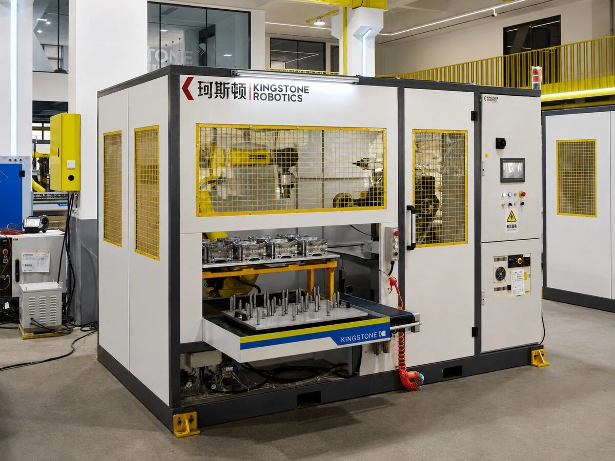
Kingstone Robotics develops customized grinding, polishing and deburring cells around the customer's actual part and process requirements.
During project evaluation, our engineers consider the robot, abrasive equipment, fixture, processing sequence, loading method, safety system and dust-control requirements as one integrated solution. The fixture is developed together with the robot layout and process testing so that the part remains stable and the required surfaces remain accessible.
Depending on the application, the complete system can include:
-
Industrial robot and controller
-
Grinding, polishing or deburring equipment
-
Custom workpiece grippers and fixtures
-
Rotary tables or servo positioners
-
Part-presence and clamp-status sensors
-
Automatic loading and unloading equipment
-
Safety enclosure and dust collection
-
Process programming and production testing
For a project evaluation, manufacturers can contact Kingstone Robotics and provide part drawings, photos, samples and production requirements.
Conclusion
In robotic grinding and polishing, repeatable robot motion is only useful when the workpiece is also presented repeatably.
A well-designed fixture locates the part, supports processing forces, protects important surfaces and gives the tool clear access. It can reduce part-to-part variation, simplify loading and make process adjustments more predictable. A poor fixture can create quality problems that cannot be solved by changing the robot program alone.
For this reason, fixture design should be treated as a core part of the robotic finishing process from the first sample test through final production validation.
Frequently Asked Questions
1. Does every part require a custom fixture for robotic polishing?
Most parts require a fixture or gripper designed around their geometry, processing surfaces and contact forces. Similar parts may share a modular fixture, but the locating and clamping method still needs to be verified for each model.
2. Can one fixture process several product models?
Yes, when the products share stable locating features and similar dimensions. Replaceable nests or adjustable locating components can support faster changeover. A universal fixture should not be used if it reduces rigidity, positioning accuracy or tool access.
3. Is manual, pneumatic or hydraulic clamping better?
The best method depends on production volume, part size, required clamping force and loading method. Manual clamps can suit lower volumes, while pneumatic or hydraulic systems can provide faster and more consistent operation for repeated production.
4. Can robot vision replace a fixture?
Vision can help identify part position or compensate for some variation, but it does not normally replace the mechanical support needed during contact grinding or polishing. The workpiece must still resist movement and vibration when the tool applies force.
5. Can an existing manual polishing fixture be reused?
Sometimes, but it must be checked for repeatable positioning, rigidity, robot access, collision clearance, loading safety and resistance to abrasive dust. A fixture designed for a manual process may need modification before it is suitable for robotic production.
6. What causes a robotic polishing fixture to lose accuracy over time?
Common causes include wear at locating points, loose fasteners, damaged contact pads, dust accumulation and worn clamp components. Routine cleaning and inspection should be included in the production maintenance plan.