English
 Español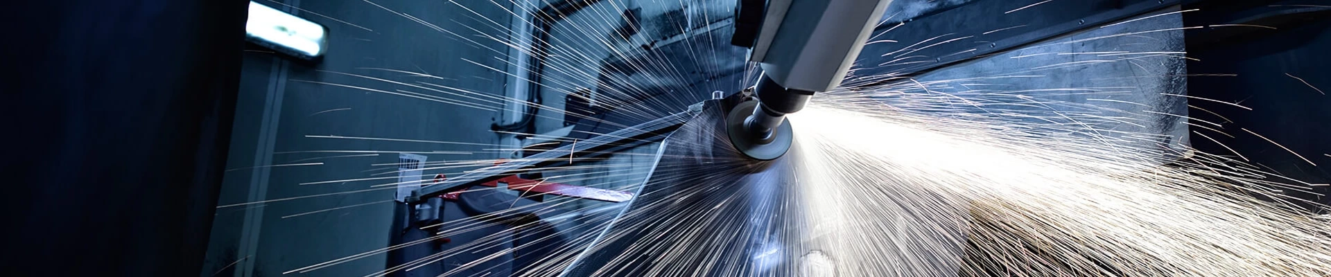
Robotic Weld Grinding: A Practical Guide to Automated Weld Seam Removal
Welded metal parts often require an additional finishing process before polishing, coating, painting or final assembly. Raised weld beads, spatter and uneven transitions can affect appearance, assembly accuracy and the quality of downstream surface treatment.
Manual weld grinding offers flexibility, but the result depends heavily on the operator’s experience, grinding angle, contact pressure and working speed. It can also expose workers to dust, sparks, noise and continuous vibration.
A properly designed robotic grinding system can automate repeated weld-seam removal and surface blending. However, successful automation requires more than programming a robot path. The abrasive process, workpiece variation, contact force, fixture, tool wear and required final surface must all be considered together.
What Is Robotic Weld Grinding?
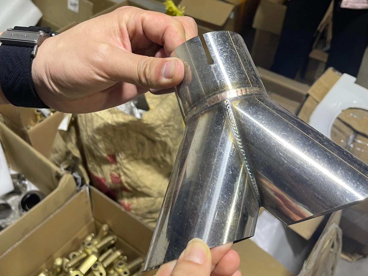
Robotic weld grinding uses an industrial robot and abrasive equipment to remove or blend selected areas of a weld bead. Depending on the application, the objective may be to:
-
Reduce a raised weld bead to a specified profile
-
Blend the weld smoothly into the surrounding parent material
-
Remove welding spatter and local surface irregularities
-
Prepare the welded area for polishing, coating or painting
-
Produce a more uniform visual finish across repeated parts
Weld grinding is different from deburring and final polishing. Deburring mainly removes sharp edges or small projections, while polishing refines the surface and creates a smoother or more decorative finish. Our guide to robotic deburring, grinding and polishing explains how these processes serve different purposes.
The goal of robotic weld grinding is not simply to remove as much material as possible. The system must remove the required amount while avoiding excessive grinding of the weld or surrounding material.
For structural or safety-critical parts, the acceptable weld profile and material-removal limits must be defined by the manufacturer’s engineering and quality requirements before automation begins.
Why Manual Weld Grinding Is Difficult to Control
Variation Between Welds
Even when parts are produced using the same welding process, the position, height and width of the weld bead may vary. Heat distortion can also change the shape of thin or fabricated components.
A fixed grinding path may work well on one part but remove too much or too little material from the next if the incoming weld variation is not understood.
Inconsistent Grinding Pressure
Manual grinding pressure changes with operator posture, fatigue, tool condition and access angle. Excessive pressure can create gouges, flat spots, heat discoloration or excessive material removal. Insufficient pressure may leave raised areas that require rework.
Difficulty Maintaining the Correct Angle
The contact angle between the abrasive and the weld affects stock removal and surface appearance. Curves, corners, tubes and intersecting surfaces make it difficult to maintain the same angle throughout the process.
Dependence on Skilled Operators
Experienced weld-grinding operators require training and process knowledge. When production volume increases or skilled workers are unavailable, weld finishing can become a manufacturing bottleneck.
Dust, Sparks, Noise and Vibration
Grinding produces abrasive dust, metal particles, sparks, noise and vibration. Automating the process can help separate operators from the immediate grinding area, but the robotic cell must still include suitable guarding, dust control and material-specific safety measures.
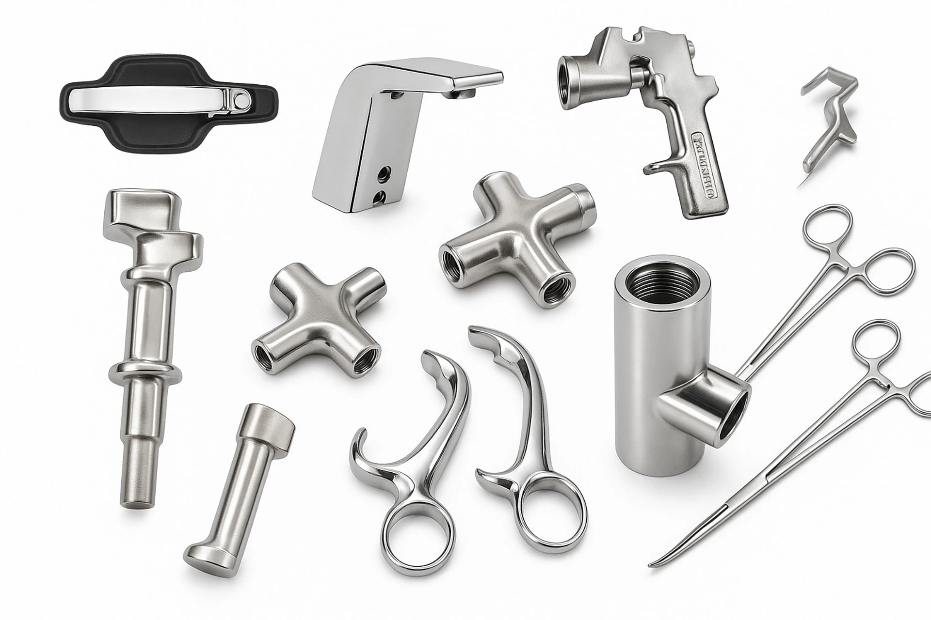
Which Welded Parts Are Suitable for Robotic Grinding?
Robotic weld grinding is usually most practical when the same part or product family is processed repeatedly and the required finished surface can be clearly defined.
Typical applications include:
| Industry or product | Typical grinding requirement |
|---|---|
| Bathroom and door hardware | Blending welds on towel bars, rails, handles and tubular components before polishing or plating |
| Automotive components | Grinding repeated welds on brackets, frames, pipes and fabricated assemblies |
| Metal furniture | Smoothing welded joints on chair frames, table bases and decorative structures |
| Industrial equipment | Removing or blending weld beads on housings, frames, guards and machine components |
| Rail and transportation parts | Controlled weld-seam grinding on repeated fabricated components according to approved specifications |
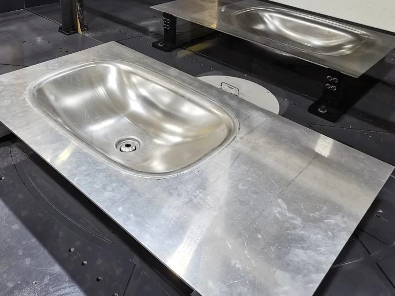
| Stainless steel products | Preparing visible welded surfaces for satin finishing, polishing or coating |
Not every welded component should be automated immediately. One-off products, extremely inconsistent welds, inaccessible internal joints or parts without a defined acceptance standard may require upstream process improvement or additional evaluation before robotic grinding is practical.
How the Robotic Weld Grinding Process Works
Although the exact sequence depends on the component, a typical automated process includes the following stages.
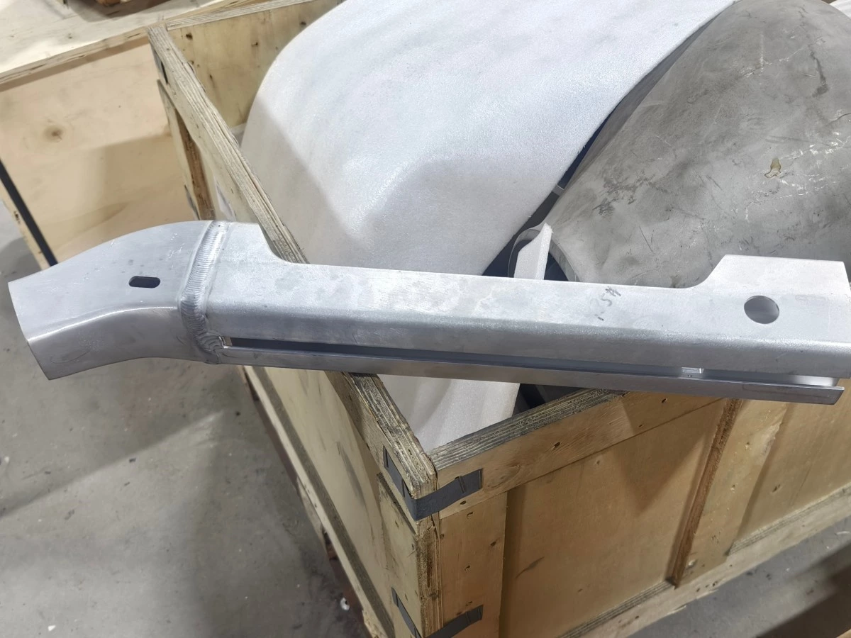
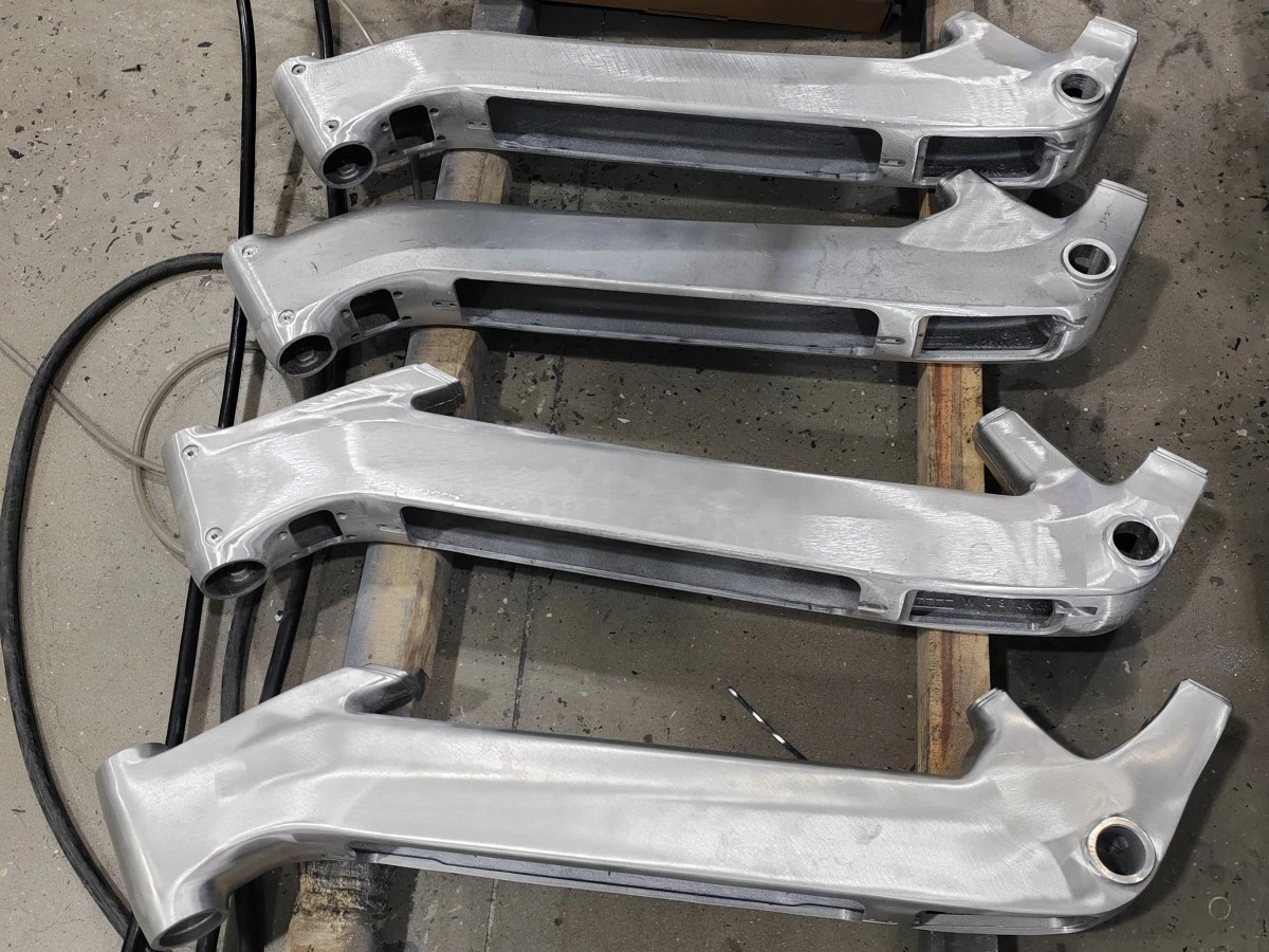
1. Define the Required Finished Condition
The manufacturer first needs to specify what the completed weld area should look like.
The target may be:
-
A weld bead reduced to a controlled height
-
A smooth transition into the parent material
-
A visually blended decorative surface
-
A specified surface texture or roughness
-
A surface ready for polishing, painting, coating or plating
An approved finished sample is often more useful than a general instruction such as “grind the weld smooth.”
2. Locate and Secure the Workpiece
The part must be placed in a repeatable position. The fixture needs to support the component against grinding forces without deforming it or blocking access to the weld.
Our guide to fixture design for robotic grinding and polishing explains how positioning, support, tool access and loading affect the final result.
3. Perform Initial Material Removal
A suitable abrasive belt, grinding wheel, flap disc or other tool removes the main raised portion of the weld. Tool selection depends on the material, weld size, geometry, access and allowed removal rate.
The robot path, approach angle, speed and pressure should be developed through actual process testing rather than selected from a standard program.
4. Blend the Weld Area
After the main bead has been reduced, a finer abrasive may be used to blend the transition between the weld and the surrounding surface.
This stage is particularly important for visible stainless steel products, bathroom hardware, furniture components and other parts that require a consistent cosmetic finish.
5. Complete Additional Surface Finishing
If the product requires grinding followed by polishing, the system may move the component to another abrasive station or change tools automatically.
A combined robot grinding and polishing unit can integrate several finishing stages when the part geometry, cycle time and quality requirements make a multi-process cell practical.
6. Inspect the Finished Area
Inspection may include visual comparison, profile measurement, surface-roughness checks or other methods defined by the manufacturer.
The inspection method should be established during process development so that the robotic program is designed around a measurable acceptance standard.
Robot-Holds-Tool or Robot-Holds-Workpiece?
There are two common configurations for robotic weld grinding.
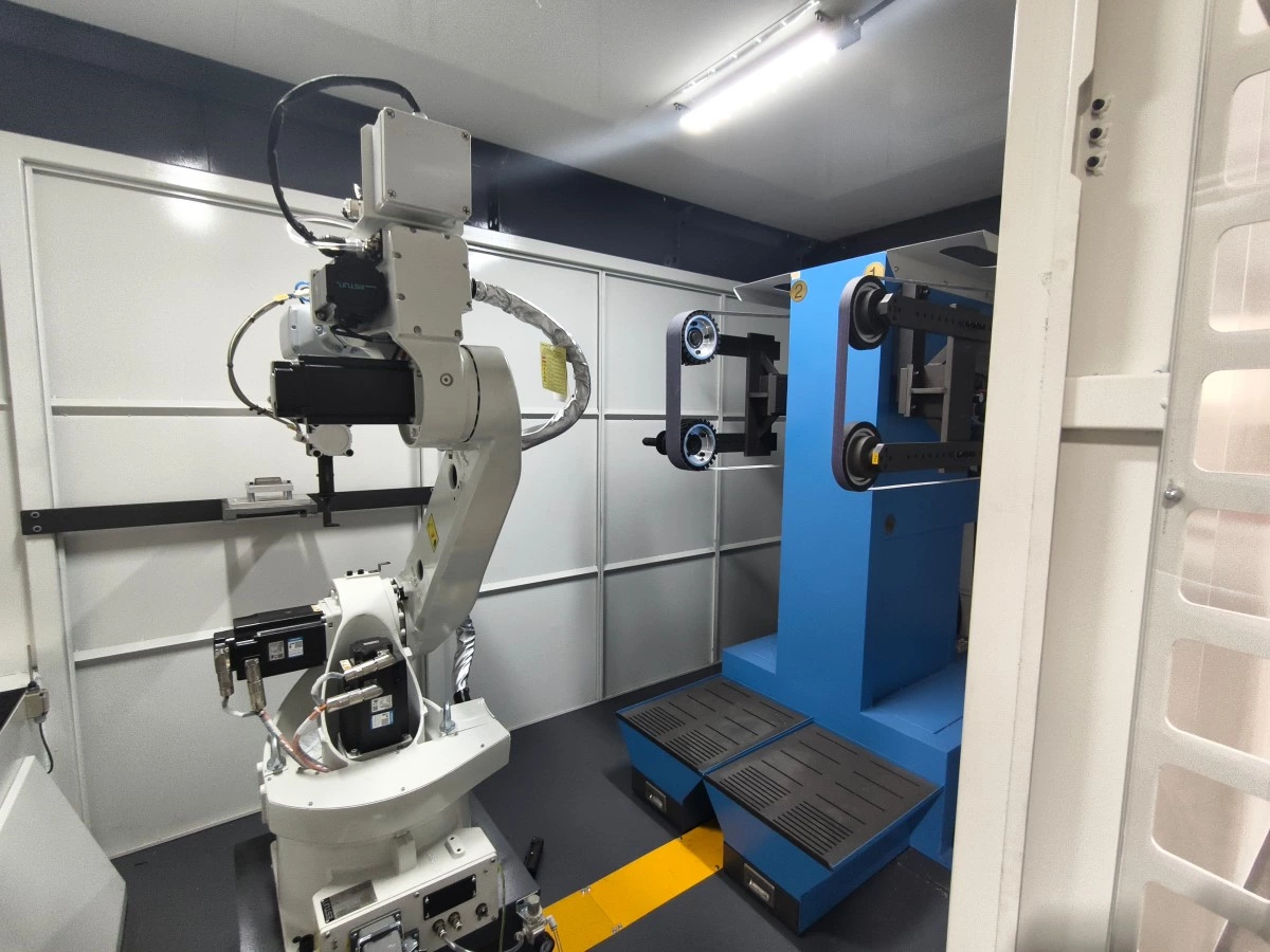
Robot Holds the Grinding Tool
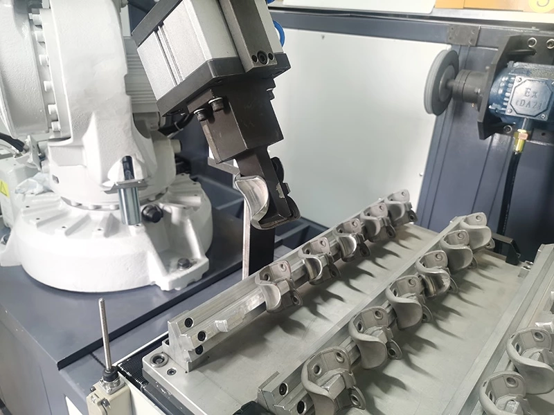
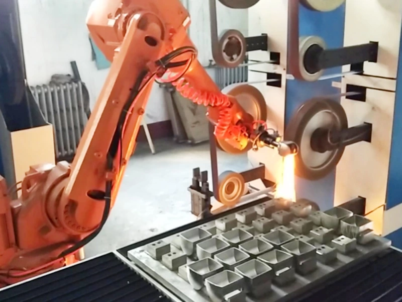
In this configuration, the workpiece remains in a fixture while the robot moves a grinding spindle, belt-grinding head or other abrasive tool along the weld.
This arrangement is often suitable for:
-
Large or heavy components
-
Long weld seams
-
Welds distributed across a fabricated assembly
-
Parts requiring a positioner to expose several sides
-
Applications where seam-location sensing may be required
The fixture or servo positioner may rotate the part so that the robot can maintain suitable tool access and contact orientation.
Robot Holds the Workpiece
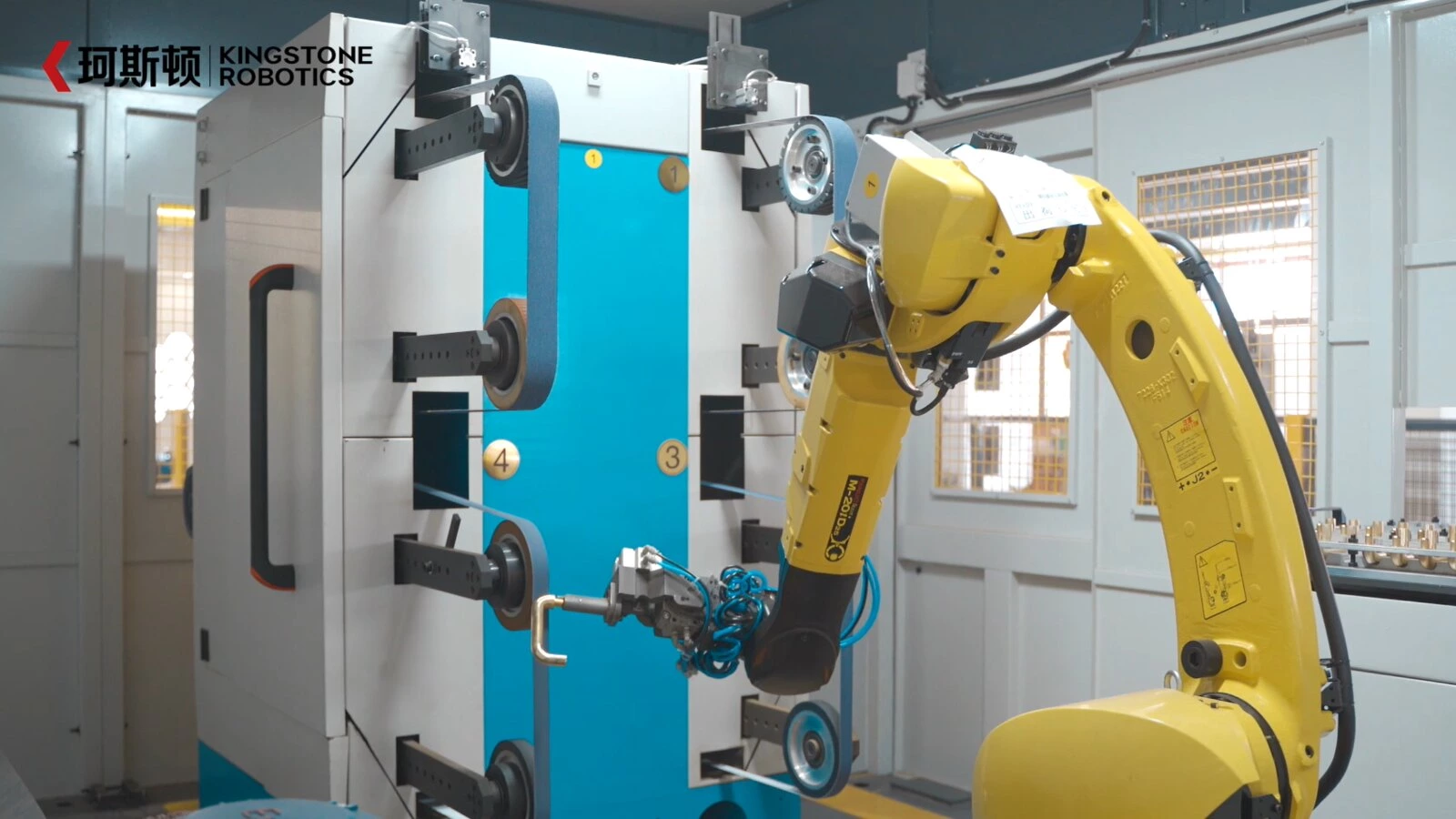
For smaller and lighter components, the robot may grip the part and present the welded area to a fixed belt sander, grinding wheel or polishing station.
This configuration can be practical for:
-
Handles and tubular hardware
-
Small welded brackets
-
Furniture components
-
Repeated product families with accessible external welds
-
Parts requiring several fixed grinding and polishing stations
The correct configuration depends on part weight, dimensions, weld locations, required tool angles, loading method and production flow.
Critical Factors in a Robotic Weld Grinding System
Weld Location and Incoming Variation
A robot repeats programmed movements accurately, but it does not automatically know that a weld has moved or changed shape.
For stable parts and repeatable welding, an accurate fixture and validated path may be sufficient. Applications with greater variation may require seam-location sensing, vision, laser measurement, tactile detection or adjustments to the upstream welding process.
Sensing should be selected according to the actual variation. Adding a complex vision system is not always necessary when the part and weld can already be presented consistently.
Contact Force and Compliance
Grinding requires physical contact between the abrasive tool and the workpiece. Small position errors can create large changes in contact pressure if the system is too rigid.
Force control or compliant tooling can help the abrasive follow normal surface variation while maintaining more stable contact. Too much force may cause gouging, overheating or rapid abrasive wear. Too little force may leave part of the weld unprocessed.
You can learn more about the relationship between pressure, abrasive wear and process stability in our article on tool-wear compensation and stable contact force.
Abrasive Selection and Process Sequence
One abrasive tool is not suitable for every stage. A weld-finishing process may use:
-
A coarse abrasive for controlled stock removal
-
A medium abrasive for profile blending
-
A finer abrasive for surface refinement
-
A polishing or non-woven finishing tool when a decorative finish is required
The sequence must match the part material and finished-surface requirement. Using an abrasive that is too aggressive can damage the parent material, while beginning with an abrasive that is too fine can increase cycle time and tool consumption.
Tool Wear Compensation
Abrasive belts, discs and wheels change as they wear. Their cutting ability, diameter and contact condition may be different after repeated cycles.
A production system therefore needs a tool-management strategy. Depending on the application, this may include:
-
Tool-life monitoring
-
Scheduled abrasive replacement
-
Path or position compensation
-
Force-based process adjustment
-
Inspection after a defined number of parts
Tool wear should be considered during process development rather than treated only as a maintenance issue.
Fixture Rigidity and Tool Access
The fixture must hold the part securely while leaving the entire weld accessible. If the part vibrates, flexes or moves during grinding, the finished profile may become uneven even when the robot follows the correct path.
Tool diameter, robot wrist clearance, approach angle, positioner movement and future abrasive replacement all need to be checked during layout design.
Dust and Spark Control
The grinding cell should include guarding and an appropriate dust-collection strategy based on the workpiece material, abrasive process and local safety requirements.
Aluminum, magnesium, titanium and other materials may require additional dust, fire or explosion-risk evaluation. Wet or dry dust collection should only be selected after considering the material, particle characteristics and complete process environment.
How to Manage Weld Variation
Automation works best when the variation entering the grinding cell remains inside a known process window.
Manufacturers can improve stability by:
-
Controlling part location during welding
-
Reducing excessive variation in weld height and position
-
Using repeatable locating surfaces in the grinding fixture
-
Testing samples from different production batches
-
Applying force control or compliant tooling where appropriate
-
Using seam-location sensing when the variation cannot be controlled mechanically
-
Defining clear limits for acceptable incoming parts
It is important to test representative parts, not only the best sample. Parts from different batches help determine whether the proposed robotic process can manage real production variation.
When Does Automated Weld Grinding Make Sense?
A robotic weld-grinding project is more likely to create value when:
-
The same parts or product families are produced repeatedly
-
Manual grinding is limiting production capacity
-
Surface quality varies between operators or shifts
-
Rework is caused by excessive or incomplete grinding
-
Skilled grinding workers are difficult to recruit
-
The process creates significant dust, vibration or ergonomic demands
-
The required finished condition can be clearly defined
-
The upstream welding process is reasonably stable
Production volume is important, but it is not the only consideration. Part complexity, current labor input, quality requirements, changeover frequency and the number of grinding stages also affect whether automation is suitable.
Information to Provide for Project Evaluation
To evaluate an automated weld-grinding application, prepare as much of the following information as possible:
-
Part photos, 2D drawings and 3D models
-
Workpiece material, dimensions and weight
-
Weld type, position, length and approximate size
-
Photos showing the weld before grinding
-
An approved finished part or clear quality standard
-
Areas that must not be ground
-
Allowed material-removal limits
-
Current manual tools and abrasive sequence
-
Typical weld and part variation
-
Daily or annual production quantity
-
Current and target cycle time
-
Number of product models
-
Required downstream process, such as polishing, coating or plating
-
Preferred manual or automatic loading method
-
Available workshop space
-
Dust-control and factory-safety requirements
Physical samples from normal production batches are especially valuable because drawings usually do not show actual weld height, spatter, heat distortion or part-to-part variation.
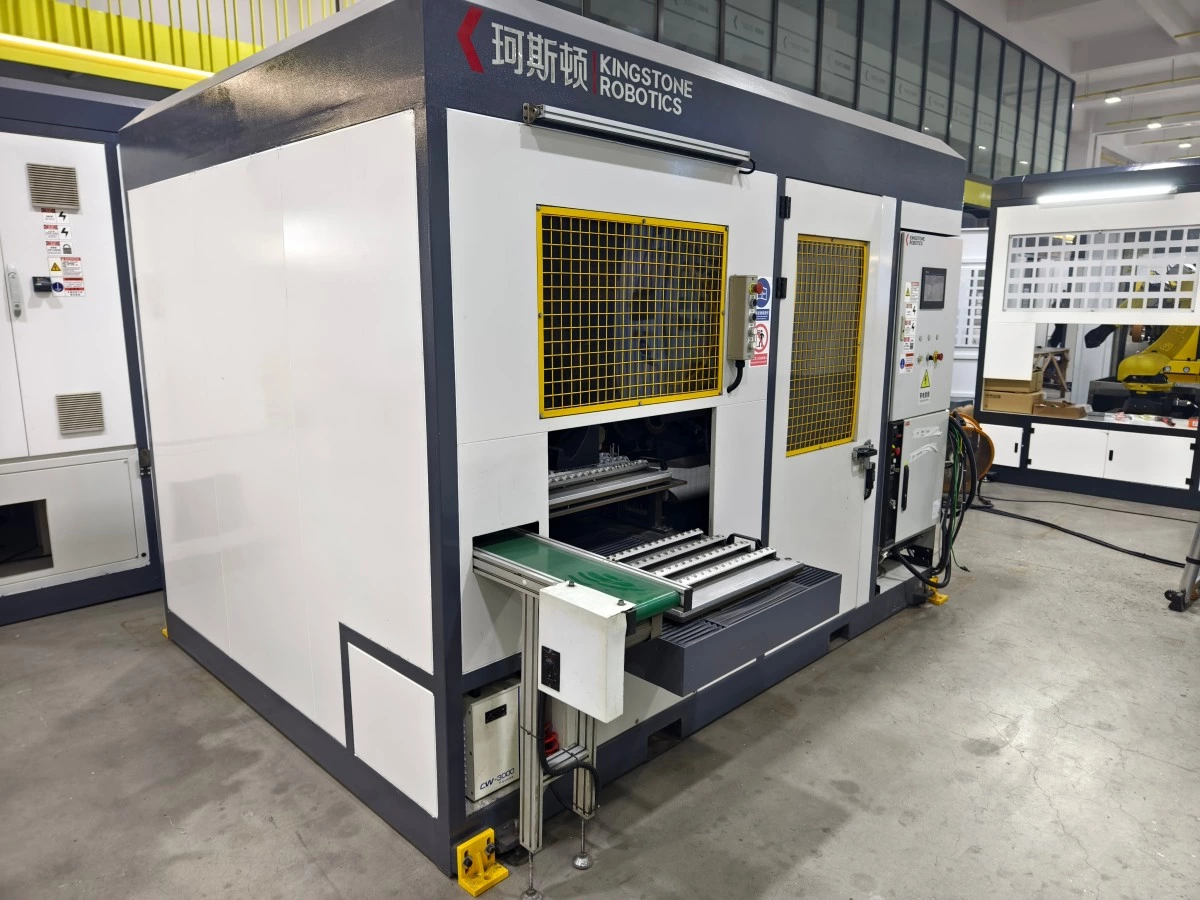
Kingstone Robotics’ Approach
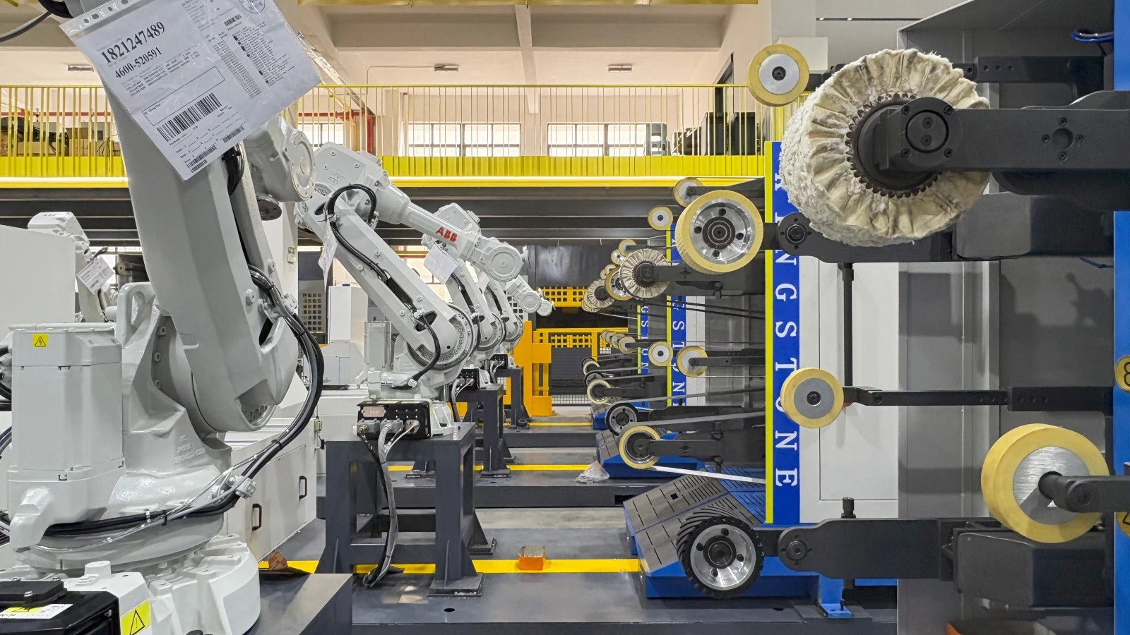
Kingstone Robotics develops customized robotic grinding systems around the customer’s actual part, weld condition and finishing requirement.
A project evaluation can include workpiece analysis, sample testing, abrasive selection, process-sequence development, robot and tool configuration, fixture design, loading method, dust control and production validation.
Depending on the application, the complete system may include:
-
Industrial robot and controller
-
Belt-grinding or spindle equipment
-
Force-control or compliant grinding tools
-
Custom fixtures and robot grippers
-
Rotary or servo positioners
-
Seam-location or part-detection sensors
-
Multiple abrasive stations
-
Safety enclosure and dust-control equipment
-
Automatic loading and unloading
-
Process programming and operator training
The purpose is not only to make the robot follow the weld. The complete system must produce an acceptable finished surface across real production parts.
Conclusion
Robotic weld grinding can turn a demanding manual operation into a more repeatable and manageable production process. Its success depends on understanding the weld, defining the required final surface and integrating the robot with suitable abrasives, contact-force control, fixtures, sensing and safety equipment.
Before selecting a system, manufacturers should evaluate their actual weld variation, product mix, production volume and downstream finishing requirements. Representative samples and a clearly approved finished part provide the best foundation for process testing.
If you are considering automated weld-seam removal or surface blending, contact Kingstone Robotics and send us your part drawings, weld photos, production requirements and finished-surface standard. Our engineering team can evaluate the application and recommend a suitable robotic grinding solution.
Frequently Asked Questions
1. Can robots grind both MIG and TIG welds?
Yes, both MIG and TIG welds can potentially be processed by a robotic grinding system. Suitability depends on the weld size, location, material, part geometry and required finished profile. Representative samples should be tested before the final system is designed.
2. Can a robot follow an inconsistent weld seam?
A robot can manage a defined amount of variation through accurate fixturing, compliant tooling, force control or seam-location sensing. If the weld position or height varies beyond the process range, the welding process may need to be improved first.
3. Will grinding weaken the weld?
Excessive grinding can reduce the weld or surrounding material. The acceptable finished profile and material-removal limit must therefore be defined by the manufacturer’s engineering and quality requirements. Safety-critical welds should be processed and inspected according to the applicable production specification.
4. Which abrasive tool is best for weld grinding?
There is no single abrasive suitable for every weld. Belt sanders, grinding wheels, flap discs and other tools may be selected according to the material, weld size, access, removal requirement and desired finish. Process testing is required to determine the correct abrasive sequence.
5. Can the same robot grind and polish a welded part?
Yes. When the product requires both weld removal and final surface finishing, one robotic cell can be designed with multiple abrasive stations or automatic tool changes. The feasibility depends on part geometry, production volume and cycle-time requirements.
6. What samples should be provided before requesting a proposal?
Provide several welded parts representing normal production variation, together with an approved finished sample whenever possible. Drawings, material information, production quantity, current grinding method and photos identifying the required processing areas are also important.