English
 Español
Robotic Deburring for Aluminum Die Castings: Flash Removal and Edge Quality
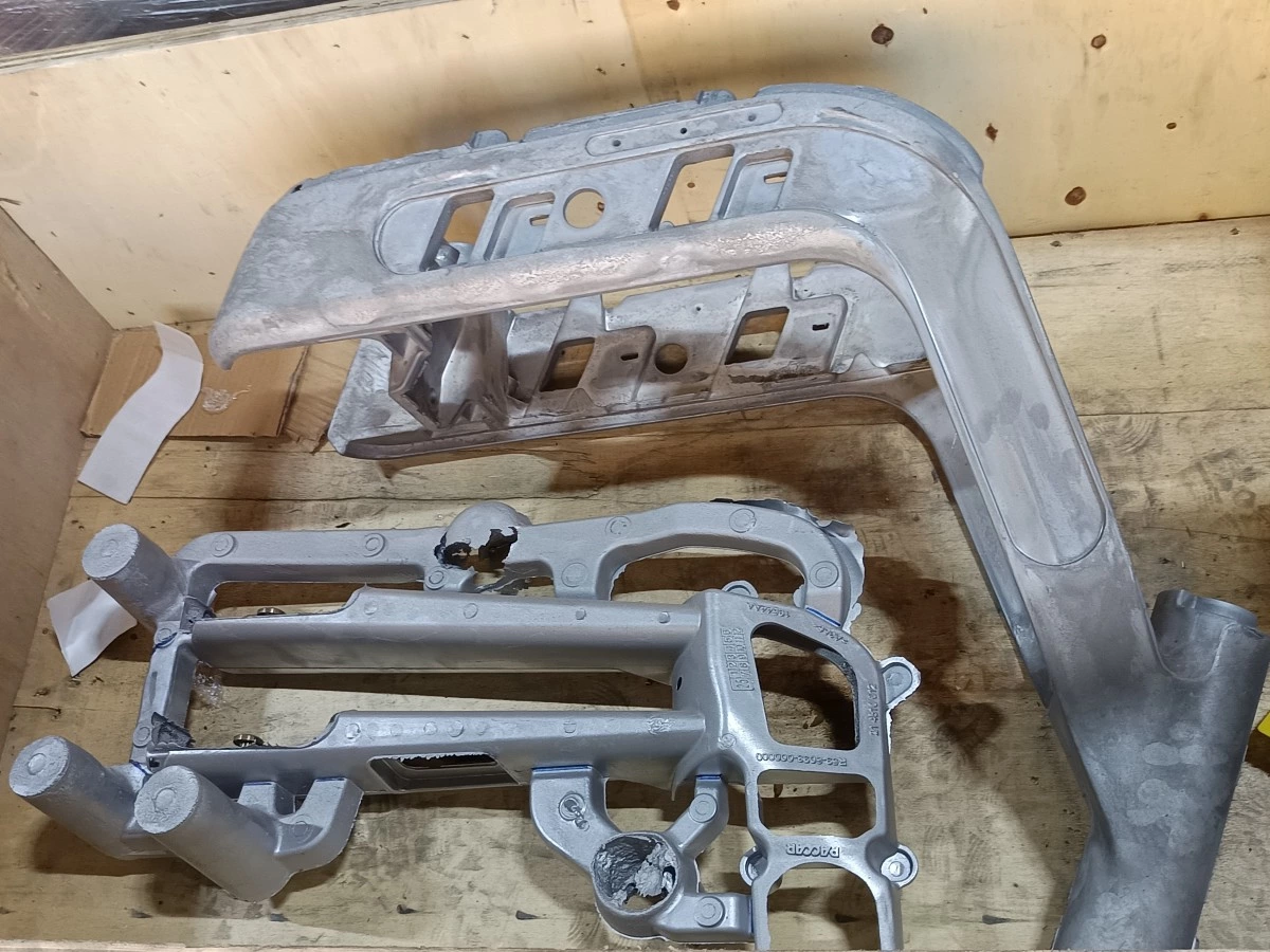
An aluminum die casting can have its main shape complete and still need careful finishing around its edges. Thin flash, residual parting-line material and burrs left by trimming or machining can interfere with assembly or leave an unacceptable edge condition.
Robotic deburring for aluminum die castings targets these local features. The goal is to remove unwanted material while retaining the dimensions and surfaces the component needs to function.
A suitable robotic deburring system combines controlled tool contact, repeatable workholding and a process matched to the incoming casting. This guide explains how to define the task and evaluate a practical automation approach.
Identify the Material That Needs to Be Removed
Begin with a marked drawing or photographs showing each treatment area. “Deburr the casting” is too broad when one component contains thin flash, a gate remnant and a precision sealing face.
| Incoming feature | Process objective | What to establish before automation |
|---|---|---|
| Thin flash along a parting line | Remove the unwanted projection | Flash location, thickness range and permitted remaining material |
| Residual material after gate trimming | Reduce the remnant to the agreed profile | Stock allowance and whether a separate cutting or grinding step is required |
| Burrs around machined holes or edges | Remove the burr without damaging the feature | Tool access and allowable edge break |
| A sharp external edge | Produce the specified edge condition | Permitted chamfer, radius or other drawing requirement |
| A visible surface requiring refinement | Improve texture or appearance | Whether an additional grinding or polishing stage is needed |
Keep bulk gate removal separate from light edge finishing when developing the process. A tool selected for a thin burr may be unsuitable for a large gate remnant.
Likewise, a deburred component does not automatically need a polished appearance. If the requirement is a controlled edge for assembly, processing the entire surface may add time without improving the required result.
Place Deburring at the Right Stage of Production
The cell must be designed around the condition in which parts actually arrive. A casting delivered after trimming presents a different task from a part that has already been drilled or milled.
One possible sequence is casting, gate and overflow removal, robotic edge finishing, machining, removal of machining burrs, and cleaning. Other parts require a different order. The correct sequence depends on which operations create burrs and which surfaces are already finished.
Identify the downstream operation before setting acceptance criteria. An assembly interface may need a controlled edge break, while a coated exterior may also require surface blending. Plan chip and dust extraction with the cell. Aluminum dust can be combustible, so collection equipment must be selected for the actual material and process following an appropriate hazard assessment.
Choose How the Robot and Workpiece Will Meet
Robot Holds the Casting
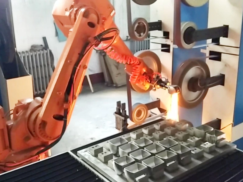
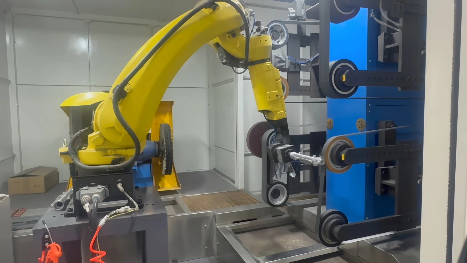
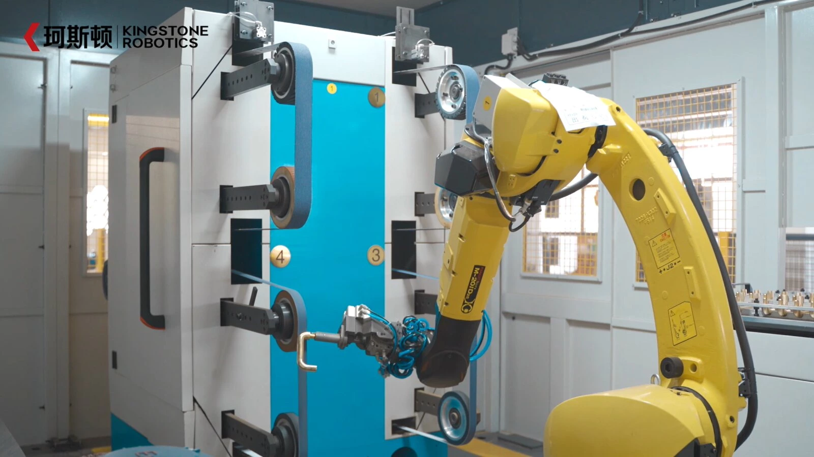
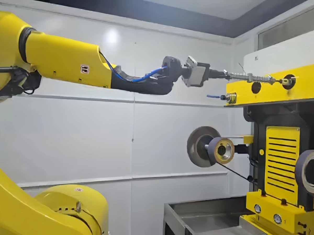
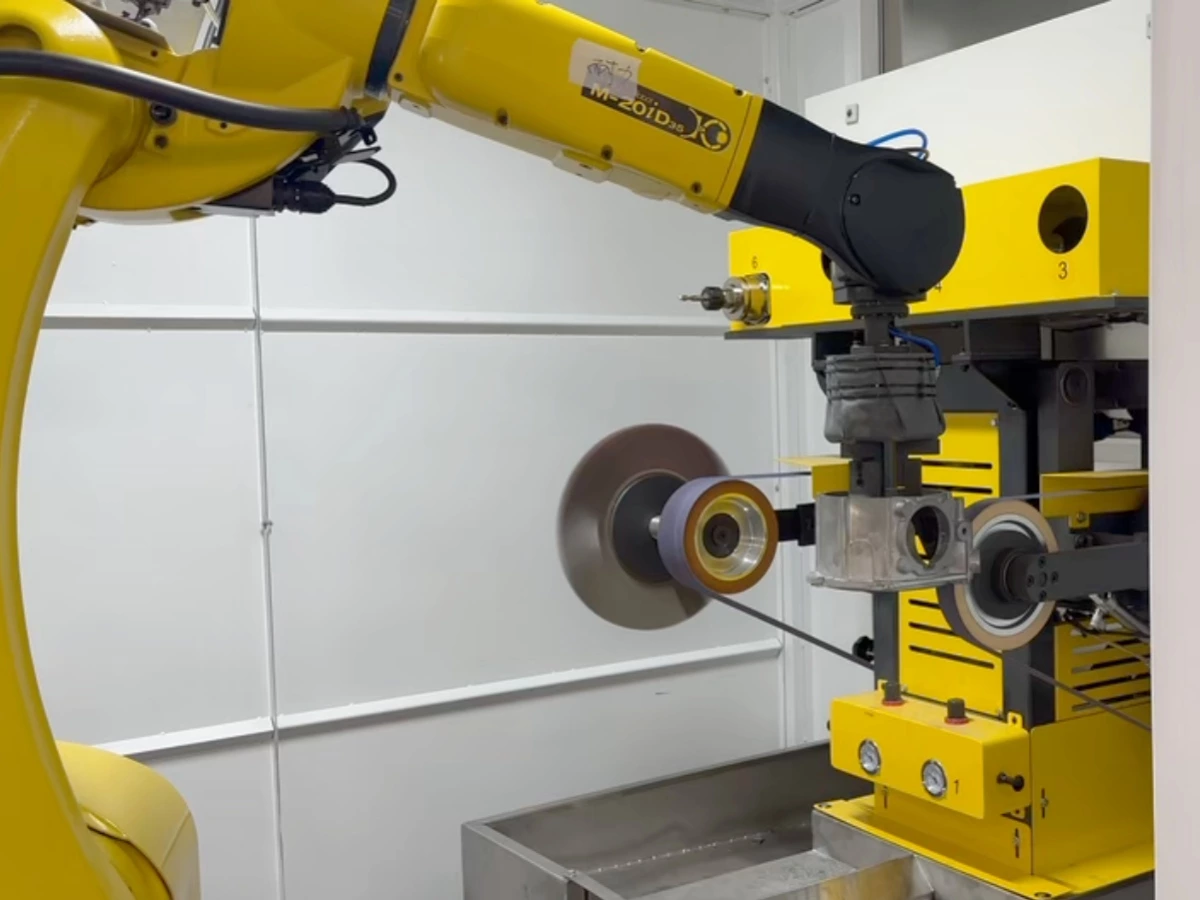
The robot grips the component and presents its edges to fixed processing stations. This arrangement can be useful when the casting is manageable in size and several sides need access to a belt, wheel or other stationary tool.
The assessment must include the combined load of the part and gripper, the center of gravity, processing forces and the robot manufacturer's wrist-load limits. A suitable payload rating alone does not establish that every processing orientation is feasible.
Robot Holds the Tool
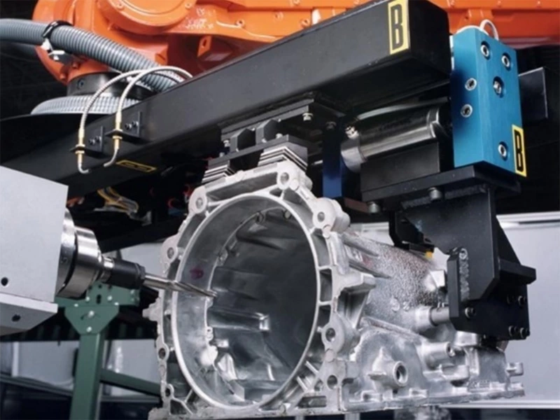
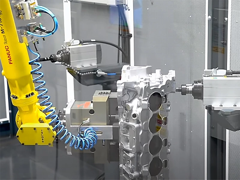
The casting stays in a fixture while the robot carries the deburring tool. This may suit a housing that is heavy, awkward to grip or easier to locate on stable mounting features.
A positioner or additional setup may be needed to expose other faces. For a related application, see Kingstone's gearbox housing grinding and deburring solution. The layout still needs to be checked against the specific casting, tool access and production requirements.
Match the Tool to the Burr and the Required Edge
Tool selection should follow the removal task. Rotary cutters, abrasive belts, deburring wheels and abrasive brushes perform differently, even when they can reach the same area.
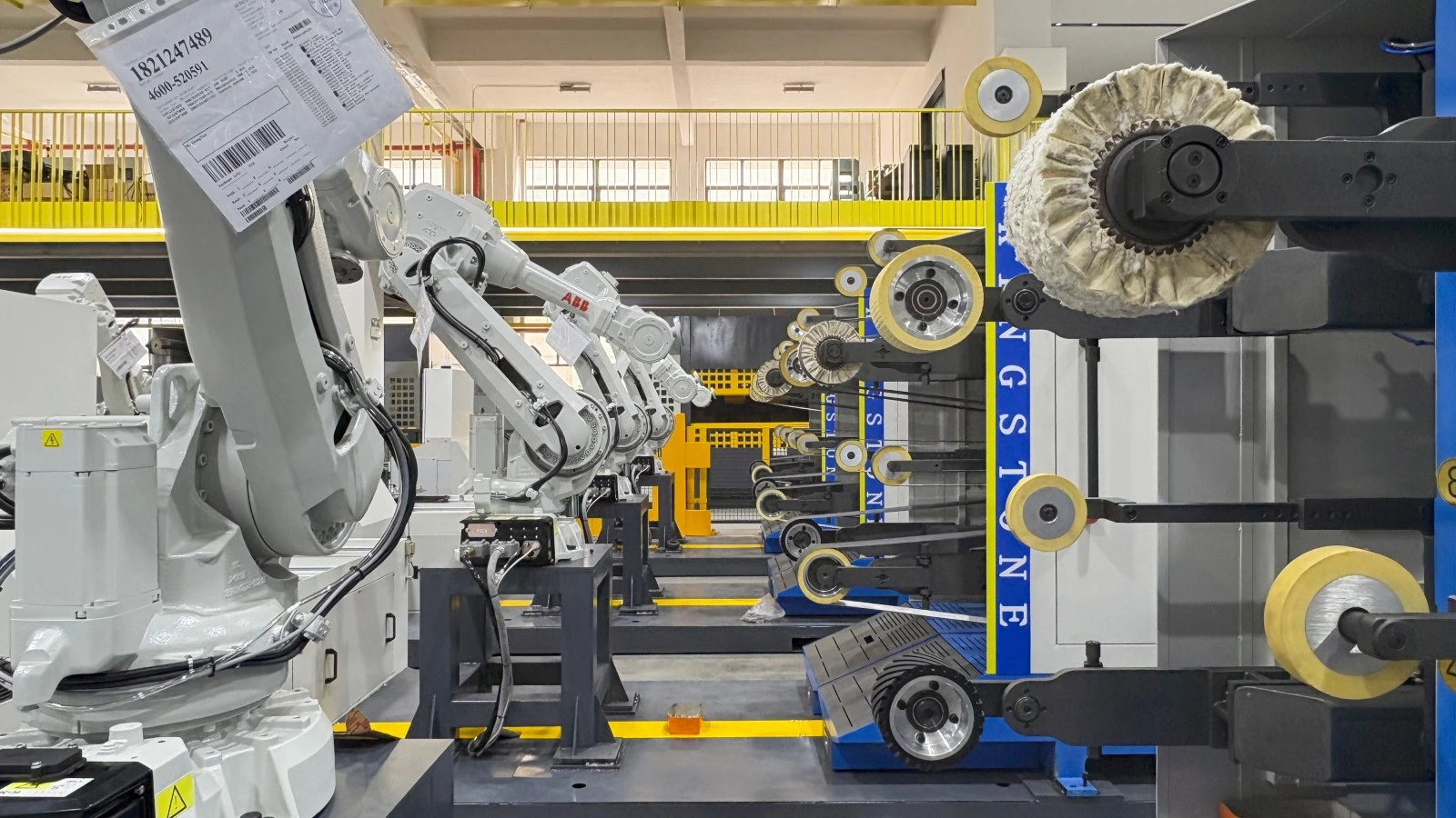
Rotary cutting tools may suit localized flash or defined edge features. Abrasive belts can be considered for accessible parting-line material and blending after trimming. Deburring wheels or abrasive brushes may suit lighter burr removal and edge refinement, depending on the material and required result.
Where the task includes more substantial abrasive removal, review a casting parts grinding configuration as part of the process discussion.
Select the exact tool, abrasive grade, speed and number of passes through trials. Check that the process removes the burr without leaving a folded lip, creating a deep local mark or rounding an adjacent feature beyond its permitted limit.
Control Variation Without Losing the Required Shape
Establish a Reliable Part Position
Locate the casting from suitable reference features and support it against the processing force. Thin walls and projecting sections need particular attention because movement during contact can change the result.
The fixture must also leave the treatment area accessible. Review locating surfaces, clamp clearance and debris accumulation together. Our guide to fixture design for robotic grinding and polishing explains these considerations in more detail.
Use Compliance and Force Control Within a Defined Range
Compliant tooling or force control can help maintain contact when the surface differs slightly from the nominal path. It cannot make unrestricted casting variation acceptable.
Establish which differences the cell is expected to accommodate, including flash size, local surface position and loading variation. Parts outside that agreed range may need rejection, rework or a different process. A tightly toleranced chamfer also requires appropriate dimensional control; a compliant tool alone does not guarantee its size.
Protect Functional Features and Manage Tool Wear
Mark sealing faces, threads, locating surfaces and other areas that must remain untouched. Specify any intentional edge break beside those features rather than allowing the finishing tool to define it accidentally.
Tool condition belongs in the control plan. A worn cutter or changing abrasive surface can affect removal even when robot motion remains identical. Establish inspection and replacement criteria, and verify any permitted compensation. See our guide to tool-wear compensation and force control for further background.
Verify Edge Quality and Complete Cell Performance
Use representative incoming castings for the trial, including relevant variation between batches or mold cavities. Compare results against the marked drawing and agreed inspection method.
Acceptance should address remaining burrs, permitted edge geometry, adjacent dimensions and any damage to protected surfaces. Where cleanliness matters, include the relevant particle or cleaning requirement. A photograph alone may not reveal a small residual burr or excessive local rounding.
Record the complete cell cycle as well as tool-contact time. Handling, clamping, repositioning and tool changes all affect output. Include any manual finishing still required after the robotic operation.
Our robotic polishing sample testing guide provides a framework that can also be used to plan and document deburring trials. Define the tested part range and remaining development work before using the results to approve a production system.
Frequently Asked Questions
Is robotic deburring the same as robotic polishing?
Deburring removes unwanted projections and establishes the required edge condition. Polishing refines surface texture or appearance. A component may need both, but they should have separate process objectives and acceptance criteria.
Can one robotic cell remove flash and finish the edge?
Yes, where suitable tools, access and cycle time allow the operations to be combined. Some castings need separate stations or an upstream trimming step. The incoming amount of material determines whether a combined process is practical.
Can robotic deburring reach internal holes and recessed areas?
It depends on the opening, tool dimensions, approach angle and fixture. Deep or obstructed features may require a specialized method or a separate operation. Include these areas in the initial feasibility review.
Will every aluminum casting use the same deburring settings?
No. Alloy, geometry, burr condition, wall thickness and edge requirements influence tool selection and process settings. Even similar parts need verification before sharing a production recipe.
Discuss Your Aluminum Casting Application with Kingstone
Kingstone Robotics develops customized robotic grinding, polishing and deburring systems. To discuss an aluminum die casting application, share the part drawing or 3D model, alloy, dimensions, weight and photographs of the areas requiring treatment.
Include the incoming condition, protected features, required edge quality, production target and current manual operations. This information helps define the scope of a process evaluation.
Contact Kingstone Robotics to discuss your component and the next steps for evaluating robotic deburring.