English
 Español
How to Reduce Edge Rounding in Robotic Polishing
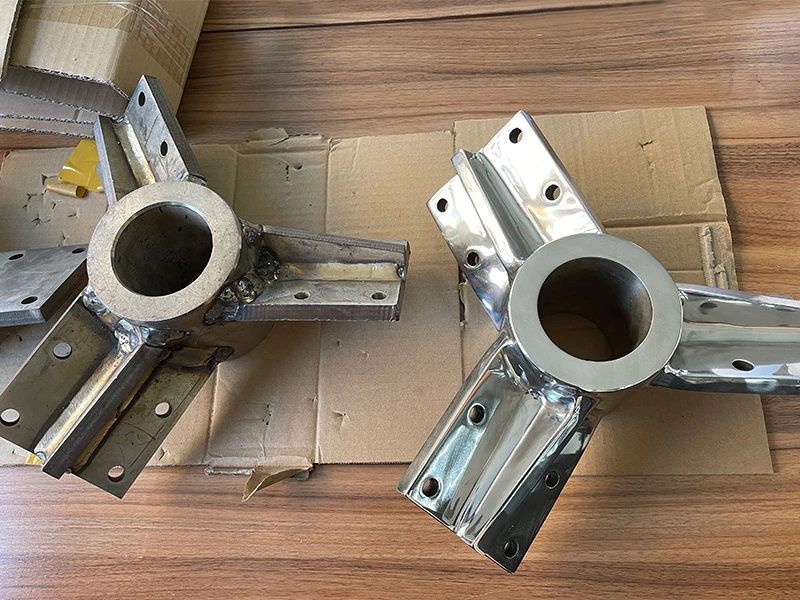
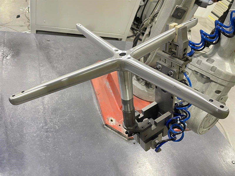
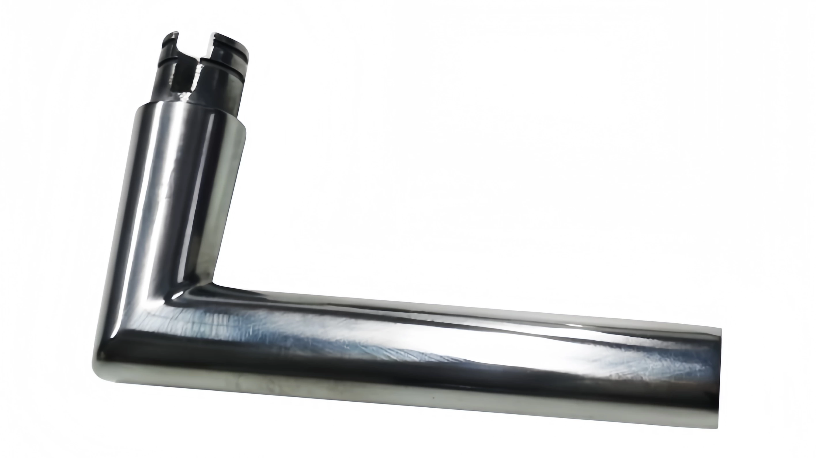
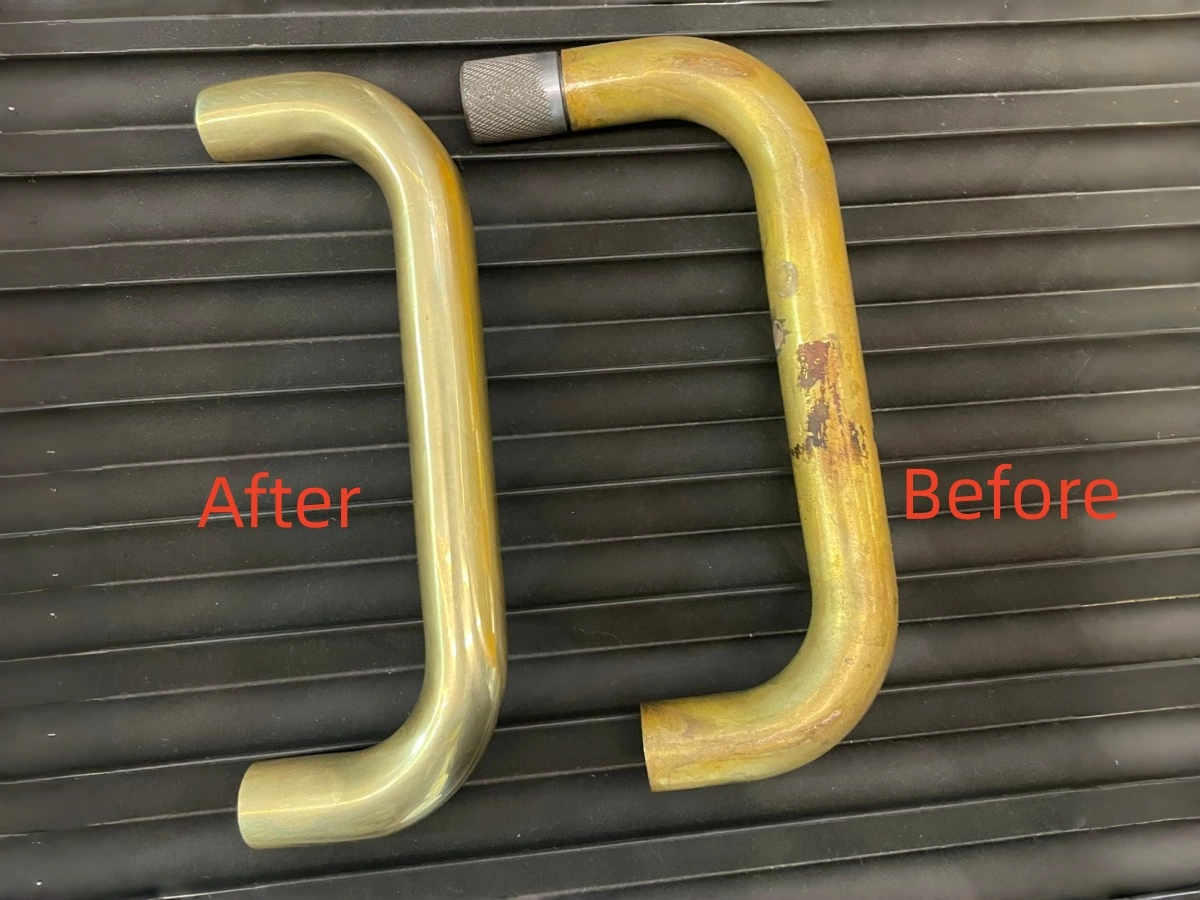
A polished part can look smooth while its edges have changed beyond the drawing requirements. A softened styling line may affect the appearance of a door handle. Excessive removal near a housing flange may affect assembly. These problems need to be addressed when the finishing process is developed.
Edge rounding occurs when finishing removes material from an edge and increases its radius. Overgrinding describes excessive material removal more broadly, including local depressions and changes in wall thickness or profile. Some applications require a controlled edge break; others require a clearly defined edge to remain.
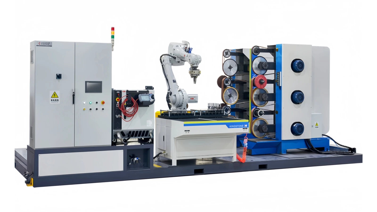
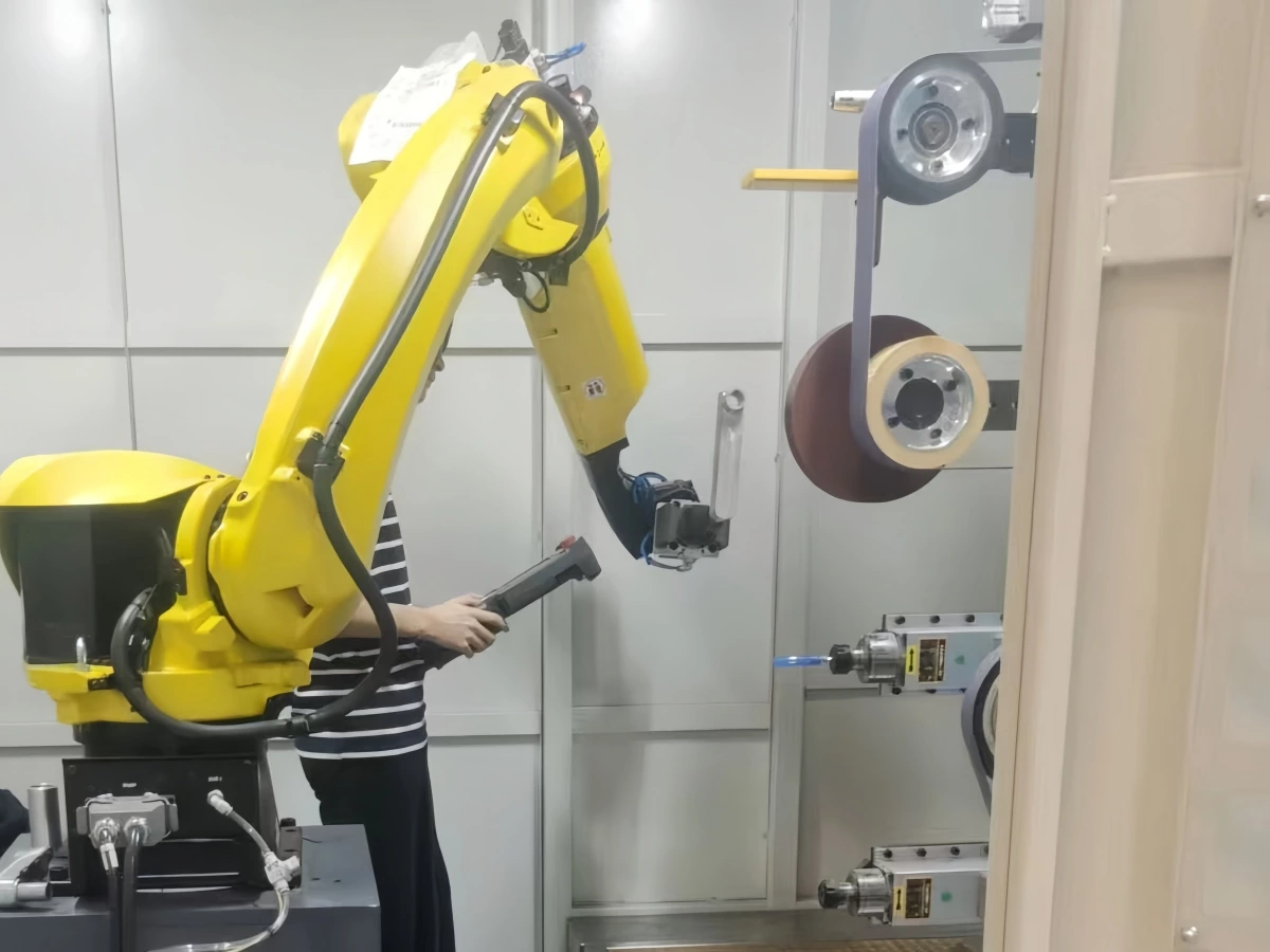
For a robotic grinding and polishing system, the starting point is to identify what should be removed and which features must be preserved. Tool contact, workholding, motion and inspection can then be planned around those requirements.
Why Edges Can Lose Shape During Polishing
The contact between an abrasive and a part changes as the tool travels from a broad surface toward a corner. The same applied force can act over a smaller contact area at an edge, increasing local pressure. A force setting that works on the main face may therefore remove too much material at the transition.
Flexible belts, pads and buffing wheels can also conform around an edge. This can help blend a curved surface, but it can soften a styling line that needs to remain distinct. The amount of wrapping depends on the tool, backing, contact force and part orientation.
Exposure time matters as well. A robot may slow near a tight turn, or adjacent passes may overlap at one location. Repeated abrasive contact can create a local defect even when the robot follows the programmed path accurately.
Define the Edge Condition Before Programming
An instruction such as “remove sharp edges” needs an agreed interpretation. Identify the required result for each area on the drawing or an annotated part photograph.
| Part feature | Requirement to define | What to inspect |
|---|---|---|
| Visible styling edge | Acceptable edge radius and visual continuity | Edge profile and appearance under agreed lighting |
| Edge requiring a burr removal pass | Burr removal and permitted edge break | Residual burrs, chamfer or radius, as specified |
| Hole, slot or locating feature | Finished dimensions and permitted contact areas | Feature size, shape and fit where required |
| Sealing face or mating surface | Areas to preserve and any allowed finishing | Relevant dimensions, flatness and surface condition |
For example, gearbox housing grinding and deburring may involve removing flash from an external casting edge while preserving a nearby machined face. Mark those areas separately so the tooling and path can be evaluated against both requirements.
Where the drawing does not define an edge condition, agree on a measurable limit or an approved reference before the trial. A reference sample should represent the intended production requirement and support the dimensional checks that apply.
Match the Contact Method to Each Surface
Support the Part Near Sensitive Features
A thin wall or projecting feature can deflect under finishing load. Check its support, the distance from the clamp to the contact point, and whether the part seats consistently after loading.
Fixture design also determines which tool angles are accessible. If a clamp blocks the intended approach, the robot may need a different grip or an additional orientation. Resolve access during process development so the chosen contact method can be used consistently.
Choose the Tool and Backing for the Required Profile
A more conformable contact may suit broad curved surfaces. A supported contact arrangement may suit a surface that needs to retain a defined profile. Small features may require a separate, suitably sized tool.
Evaluate the abrasive grade together with the contact wheel, pad or other backing. A finer abrasive changes the scratch pattern, but it can still alter an edge when contact is prolonged or the tool wraps around the corner. Select the combination through testing on the actual material and geometry.
Check Approach, Travel and Exit Motion
Review where the abrasive first touches the part, how contact changes through the pass, and where it leaves the surface. Check the actual travel speed near corners and the overlap between neighboring paths.
Where a transition requires different settings, develop a separate path segment or finishing stage. Force, orientation and travel speed can then be adjusted for that region within the selected tool's operating limits. Confirm the result on the part after each adjustment.
Use Force Control Together with Abrasive Management
Force control can help manage contact as part position or tool condition varies. However, stable force alone does not establish how much material will be removed. Abrasive condition, contact area, speed and exposure time also influence the result.
Review force control and tool-wear compensation together. A fresh belt and a used belt may cut differently; a worn wheel may also have a different diameter. Check the finished edges after a consumable change and at defined points during its usable life.
Document the approved adjustment limits and replacement criteria. If a compliant device is used, its working travel and loading direction must suit the application and follow the device manufacturer's instructions.
Troubleshoot Where and When the Defect Appears
The location and timing of unwanted removal provide useful clues. The following checks are starting points for investigation; confirm the cause through a controlled trial.
| Observation | First checks |
|---|---|
| Rounding appears mainly at outside corners | Tool wrapping, local contact area, orientation and force |
| A depression appears at the start or end of a pass | Contact engagement, disengagement and local dwell |
| One edge varies between otherwise similar parts | Part seating, clamp condition, incoming geometry and support |
| Removal increases immediately after a belt or wheel change | Fresh-tool cutting behavior, setup and compensation values |
| Geometry changes mainly during the final finish stage | Final-stage contact, pass overlap and exposure time |
Change one relevant variable at a time and retain the trial records. This makes it easier to establish which adjustment improved the result.
Verify Profile Retention During Sample Testing
Robotic polishing sample testing should include checks on the features most likely to change. A photograph of a glossy surface cannot establish whether a specified radius, wall thickness or mating dimension remains acceptable.
Prepare a trial record covering:
-
Incoming condition: Identify each sample and record the relevant dimensions, burr condition and surface defects before finishing.
-
Process stages: Inspect selected samples after stock removal and after final polishing to locate when a feature changes.
-
Finished condition: Check the specified profile, radius, chamfer or thickness with a suitable agreed method, alongside the visual finish.
-
Repeatability: Compare representative production parts and relevant abrasive conditions, including the first pieces after a consumable change.
Define acceptance for each critical area. If a surface requires a particular roughness measurement, record its location and method separately from the edge-profile check. Keep an approved part and its process settings as references for later production checks.
Frequently Asked Questions
Can robotic polishing preserve a sharp edge?
It may be possible to retain a defined edge within an agreed tolerance, depending on the geometry, access and finishing requirement. Specify the permitted edge condition and verify it through sample testing. Broad-surface polishing and a controlled edge break may need separate operations.
Does a softer polishing wheel always protect the part?
A softer wheel can conform to a curved surface, but that flexibility can also increase contact around an edge. Evaluate wheel construction, pressure, orientation and contact time together on the actual part.
Can polishing correct a part that has already been overground?
Polishing removes material and cannot restore metal that has been removed. Assess the part against its drawing requirements. Prevention depends on establishing suitable removal limits and checking sensitive features during process development.
Discuss Your Part with Kingstone Robotics
To discuss edge-sensitive grinding, polishing or deburring, contact Kingstone Robotics with your part drawings, material grade, incoming-part photographs and target finish. Mark the features that must retain their shape and include any existing edge-radius, chamfer or dimensional limits.
This information provides a practical basis for reviewing tool access, workholding, finishing stages and the sample checks required for your application.